3
2
6
5
8
7
4
1
9
Reset
Test
Trip
%
60
40
20
3
2
10
5
7
6
4
1
9
8
(t = 0 )
5
5
6
6
8
8
3
3
7
7
9
9
10
2
2
1
4
4
RD1
(t = 0 )
1
1
6
6
4
4
5
5
3
3
9
9
7
7
2
2
8
RD1
RD3
RD1
0,3...3A
0,03...0,3A
3...30A
CODICE • CODE
N° TENTATIVI /INTERVALLO TEMPO • NUMBER OF ATTEMPTS / TIME INTERVAL
RD1A - RD1D - RD3AF
3/60S
RD3AT
5/10S
RD3AU
1/10S
➊
Predisposizione
I
Δ
n soglia d’intervento
1
➋
Selettore portata x1 / x10 / x100
1
Il modello
RD1E
è dotato di un relè di preallarme con soglia inter vento fissa,
pari al 50% del valore di
I
Δ
n
selezionato
.
Controllare che il valore d’inter vento selezionato sia compatibile con le sensibi-
lità minima rilevabile dal trasformatore toroidale abbinato.
➌
•
➍
LED segnalazione
LED
spento
LED
acceso
LED
lampeggiante
➎
Pulsante di prova
Permette di simulare la condizione di allarme, l’accensione del
LED Trip
e la
commutazione del relè d’uscita.
➏
Pulsante di ripristino
➐
Selettore ripristino
Man
(manuale) = lo stato di allarme permane fino a quando l’operatore non agi-
sce sul tasto
RESET
Aut
(automatico) = ad allarme inter venuto, l’apparecchio provvede automatica-
mente al ripristino, facendo alcuni tentativi.
Terminati i tentativi, se il dispositivo non si è ripristinato, l’apparecchio entra in
stato di allarme definitivo e deve essere ripristinato manualmente.
Il lampeggio contemporaneo dei
tre LED gialli
, segnala l’esaurimento dei tentati
vi di ripristino.
Il ripristino è inibito con corrente differenziale persistente:
≅
50%
I
Δ
n impostata
➑
Selettore stato relé uscita
:
Nd
(norm. diseccitato)
sicurezza negativa -
Ne
(norm. eccitato)
sicurezza positiva.
Il relè di preallarme è sempre norm. diseccitato
(mod. RD1E)
.
➒
Predisposizione ritardo intervento
ATTENZIONE !
Selezionando la soglia d’inter vento
nella posizione 0,03 viene automaticamente escluso il ritardo
inter vento, indipendentemente dalla posizione del selettore di por tata
➋
.
Per predisporre soglia di inter vento
I
Δ
n = 30mA con inter vento istantaneo
selezionare 0,03 e accer tarsi che il selettore
➋
sia in posizione x1.
➓
Indicazione istantanea della corrente differenziale
(in % del valore
I
Δ
n impostato).
ISTRUZIONI DI CABLAGGIO
• La posizione di fissaggio risulta completamente indifferente ai fini del funziona-
mento.
•
Le operazioni di predisposizione (soglia intervento, tempo ritardo, ecc.) devono
essere effettuate con apparecchio non alimentato.
• Rispettare scrupolosamente lo schema d'inserzione, una inesat tezza nei collegamenti è ine-
viitabilmente causa di funzionamento anomalo o di danni all'apparecchio.
• L'ottenimento della piena funzionalità del sistema di protezione differenziale è legato alle mo-
dalità di installazione, per cui si consiglia:
☞
Ridurre al minimo la distanza tra toroide e relè
☞
Utilizzare cavi schermati o intrecciati per la loro connessione
☞
Evitare di disporre i cavetti di connessione toroide-relè parallelamente a conduttori
di potenza
☞
Evitare di installare toroide e relè in prossimità di sorgenti di campi elettromagneti
ci intensi
(grossi trasformatori).
☞
Solo i conduttori attivi attraversano il toroide (dis.
D1
)
☞
Utilizzando cavo schermato, l’armatura deve essere collegata a terra come da
(dis.
D2
)
☞
I conduttori devono essere posizionati al centro del toroide (dis.
D3
).
■
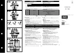
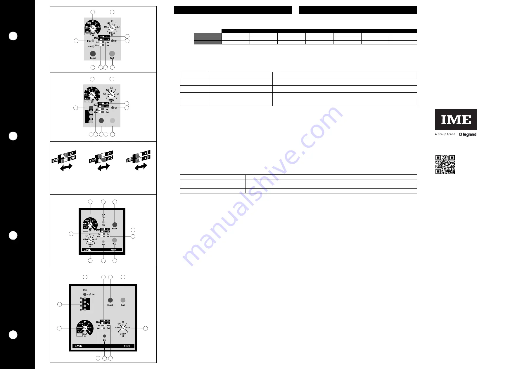
➊
Setting intervention threshold
I
Δ
n
1
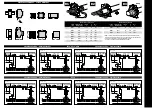
➋
Range selector x1 / x10 / x100
1
Model
RD1E
has a pre-alarm relay with fixed inter vention threshold equal to
50% of selected
I
Δ
n
value
.
Check that selected inter vention value matches the lowest sensibility detecta -
ble by the connected ring current transformer.
➌
•
➍
Signaling LED
LED
off
LED
on
LED
blinking
➎
Test key
It allows to simulate alarm condition,
LED Trip
switching on and output relay
switching.
➏
Reset key
➐
Automatic-manual reset switch
Man
(manual) = the alarm stays until the operator doesn’t act on
RESET
key
Aut
(automatic) = when alarm occurred, this unit automatically resets, making
some attempts.
When attempts are over, if the device didn’t reset, the meter enters the definiti
ve alarm state and it has to be manually reset.
The simultaneous blinking of the
three yellow LED’s
signals that reset attempts
are over.
Reset is not possible with persistent residual current:
≅
50%
I
Δ
n.
➑
Switch for state of output relay: Nd
(normally de-energised)
negative security
Ne
(normally energised)
positive security.
Pre-alarm relay is always normally de-energized
(mod. RD1E).
➒
Setting intervention delay
ATTENTION !
Selecting the inter vention threshold
on position 0,03 the inter vention delay
is automatically excluded, independently of position of range selector
➋
.
To set inter vention threshold
I
Δ
n = 30mA with istantaneous inter vention,
select 0,03 and make sure that selector
➋
is on position x1.
➓
Instantaneous display of earth leakage current
(in % of loaded
I
Δ
n value)
INSTRUCTIONS FOR WIRING
• Mounting position do not affect in any way the proper working.
•
Setting operations (intervention threshold, delay time, etc.) must be carried
out with non-fed meter.
• Please carefully follow the wiring diagram; an error in connecting the relay may give
rise to irregular working or damages.
• The achievement of differential protection system full functionality is bound to the
mounting way;therefore we suggest:
☞
To reduce as much as possible the distance between ring current transformer
and relay.
☞
To use only shielded or twisted cables for their connection
☞
To avoid in placing ring current transformer-relay connection cables parallelly to
power wires
☞
To avoid in mounting ring current transformer and relay near sources of intense elec-
tromagnetic fields
(big transformers)
.
☞
Pass active conductor only through toroid (draw
D1
)
☞
When using blind cable, ensure ground connection of armature (draw
D2
)
☞
Ensure the central positioning of conductor through toroid (draw
D3
).
■
0,03
0,05
0,075
0,1
0,15
0,2
0,3
x1
30mA
50mA
75mA
100mA
150mA
200mA
300mA
x10
300mA
500mA
750mA
1A
1,5A
2A
3A
x100
3A
5A
7,5A
10A
15A
20A
30A
I
Δ
n
On
Trip / Fail
•
•
Assenza tensione alimentazione ausiliaria o apparecchio fuori servizio
Lack of auxiliar y voltage supply or out of order meter
✺
•
Sorveglianza
• Super vision
✺
✺
Allarme
• Alarm
✺
•
✺
•
✺
Interruzione collegamento toroide - relè
Connection breakdown between relay and ring current transformer
•
✺
•
✺
•
✺
DESCRIZIONE FRONTALE
FRONT DESCRIPTION
Istruzioni d’uso
User’s Guide
RD1A
RD3A
RD1D
RD1E
BTicino SpA
Viale Borri, 231
21100 Varese - ITALY
www.imeitaly.com
LE12562AA
10/20 - 01 IM


