KEOR T EVO
Installa
tion & Oper
ation M
anual
Description of the Symbols Used in the Manual
This symbol points out the instructions which are especially important.
This symbol points out the risk of electric shock if the following instruction is
not followed.
This symbol points out the instructions, which may result with injury of the
operator or damage of the equipment if not followed.
All packing material must be recycled in compliance with the laws in force in the
country where the system is installed.
Description of the Symbols Used in the Manual
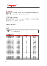
UPS: Uninterruptible Power Supply
ESD: Emergency Switching Device
RS232: Serial Communication Protocol
RS485: Serial Communication Protocol
MODBUS: Modicon Communication Protocol
SNMP: Simple Network Management Protocol
V: Volt
A: Ampere
P: Power
For Mains Supply, Auxiliary Mains Supply, Output, Battery Circuit Breaker and Maintenance Bypass Circuit
Breaker;
“ON”: Closing the Circuit
“OFF”: Opening the Circuit
29
29
KEOR T EVO
Installa
tion & Oper
ation M
anual
6.3.1.1.
Earth Connection
6.3.1.2.
Mains Supply (Rec
tifier) C
onnection
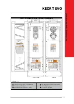
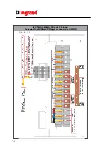
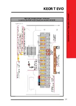
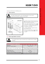
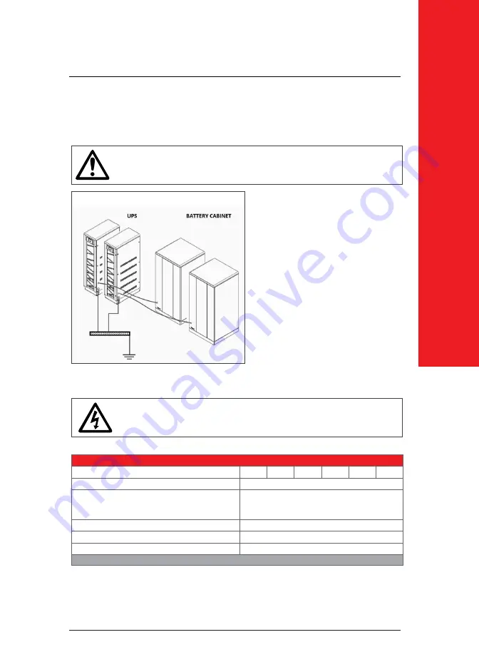
Connections shall be made in the following order;
Figure.6.3.1.1-1
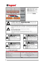
The device shall be earthed for a safe and reliable operation. Connect the PE/
PB ground terminals before connecting any other cable.
The installation and adjustment of distribution panel should be done by specialized
technician.
Input Mains Supply’s Protective Earth terminal
PE
of the UPS shall be connected to the ground
with a low impedance connection.
As the Auxiliary Supply Protective Bonding
PB
and Input Mains Supply’s Protective Earth
PE
terminals are short-circuited inside UPS, it is
not needed any connection.
Load ground should be connected to output
PB terminal of the UPS.
If there is an external battery cabinet present,
it should be grounded via battery
PB
terminal
of the UPS.
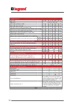
Electrical Characteristics - Rec
tifier I
nput
Model (kVA)
10
15
20
30
40
60
Rated mains supply voltage (V)
400 (3Ph+N+PE)
Voltage tolerance (V) (ensuring battery recharge)
208-459 (at half Load, without battery recharge)
338-459 (at full Load, with battery recharge)
Rated frequency (Hz)
50/60
Frequency tolerance (Hz)
from 45 to 65
Power factor (input at full load and rated voltage)
≥ 0,99
Table.4

