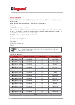
Important Notices!
Thank you for choosing LEGRAND UPS System to supply your Critical Application.
This manual contains important information about commissioning, usage and technical properties of the
UPS. It also contains safety information for operator and instructions to secure your critical load. Applying
the recommendation detailed in this manual is necessary to use UPS safely and correctly.
The manufacturer reserves the rights to change the t
echnical specifica
tions
and design without notice.
LEGRAND reserves the rights to change the information in this document
without notice. Refer to
http://ups.legrand.com/
web site to dowload last
release and translations.
Units that are labelled with a CE mark comply with the Standard: EN 62040-1 and EN 62040-2.
Read the manual completely before working on this equipment!
Keep this manual in UPS’s front cover’s pocket for easy consultation!
Reproduction, adaptation, or translation of this manual is prohibited without prior
written permission of LEGRAND Company, except as allowed under the copyright laws.
30
30
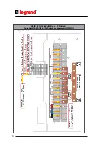
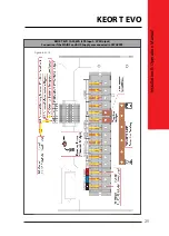
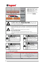
Connect the phase cables to X1
MAINS SUPPLY: X1/L1 - X1/L2 -
X1/L3
terminals, the neutral to X1
MAINS SUPPLY: X1/N
terminal.
Cables must be protected by fuses
or MCCB, refer to Section 4.4
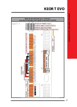
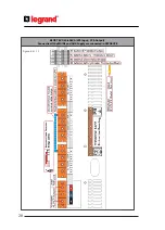
If auxiliary supply exists, remove all phase bridges
.
When used, the
residual current earth leakage protection system must be common for the
two AC inputs and in-stalled upstream.
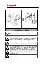
According to EN 62040-1, the user should place a warning label on the input distribu-
tion panel and the other primary power isolators, in order to prevent the risk of voltage
backfeed.
This label is supplied with the Installation Manual. It indicates:
RISK OF VOLTAGE BACKFEED
• Isolate Uninterruptable Power Supply before working on this circuit.
• Then check for Hazardous Voltage between all terminals including the protective
earth (PE).
WARNING
WARNING
WARNING
EN
IT
FR
RISK OF BACKFEED
BACK FEED RISCHIO
RISQUE DE RETOUR DE TENSION
Before working on this circut
isotale Uninterruptible Power System (UPS),
Then check for hazardous Voltage between
all terminals includig the protective earth
(PE)
Prima di intervenire su questo circuito
isolare I’UPS dalla rete .
Controllare la prensenza di tensioni
pericolose tra tutti i terminali
Avant de travailler sur le circuit électrique
İsoler I’ alimentation sans interruption (ASI)
Puis vér
ifier s
’ il y a présense de tension
dangereuse entre toutes les bornes inclua
n
t
la
connexion de terre.
WARNING
DE
RÜCKSPANNUNG RISIKO
Bev
or Sie einen Eingriff am G
rat
vornehmen trennen Sie die USV - Anlage
vom Netz.
Überprüfen Sie auf geharlichte spanunngen
zwischen den Anschlüssen und der
Shutzerde (PE).
..
..
6.3.1.3
.
Auxiliary Supply Connection
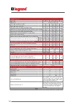
Electrical Characteristics - Bypass
Model (kVA)
10
15
20
30
40
60
Bypass frequency slew rate
2 Hz/s settable from 1 to 3 Hz/s
Bypass rated voltage
Nominal output voltage ±18% (settable)
Bypass rated frequency
50/60 Hz (selectable)
Bypass frequency tolerance
±3Hz
Table.5
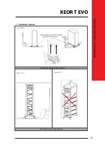
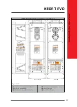
KEOR T EVO
40-60kVA
KEOR T EVO
10-30kVA

