KEOR T EVO
Installa
tion & Oper
ation M
anual
Description of the Symbols Used in the Manual
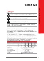
This symbol points out the instructions which are especially important.
This symbol points out the risk of electric shock if the following instruction is
not followed.
This symbol points out the instructions, which may result with injury of the
operator or damage of the equipment if not followed.
All packing material must be recycled in compliance with the laws in force in the
country where the system is installed.
Description of the Symbols Used in the Manual
UPS: Uninterruptible Power Supply
ESD: Emergency Switching Device
RS232: Serial Communication Protocol
RS485: Serial Communication Protocol
MODBUS: Modicon Communication Protocol
SNMP: Simple Network Management Protocol
V: Volt
A: Ampere
P: Power
For Mains Supply, Auxiliary Mains Supply, Output, Battery Circuit Breaker and Maintenance Bypass Circuit
Breaker;
“ON”: Closing the Circuit
“OFF”: Opening the Circuit
1
1
KEOR T EVO
Installa
tion & Oper
ation M
anual
1. FOREWORD
3
1.1.
Overview
3
1.2.
Manual
3
2. WARRANTY
5
2.1.
Terms of Warranty
5
2.2.
Out of Warranty Terms and Conditions
5
3. SAFETY
6
3.1.
Description of the Symbols Used on the Labels Applied to the UPS
6
3.2.
Individual Protective Gear
6
3.3.
Important Notice for UPS
7
3.4.
Important Notice for Battery
8
3.5.
Emergency interventions
8
4. OPERATION MODES
9
4.1.
Online Mode
9
4.2.
Battery Mode
10
4.3.
Bypass Mode
11
4.4.
Eco Mode
12
4.5.
No Operation
12
4.6.
Operation with Maintenance Bypass
12
4.7.
Operation with External Maintenance Bypass (Optional)
12
5. REQUIREMENT
13
5.1.
Transportation
13
5.2.
Placement
13
5.3.
Storage
15
5.4.
Electrical Requisites
15
6. INSTALLATION
18
6.1.
Models and Dimensions
18
6.2.
Unpacking Procedure
19
6.3.
Installation Procedures and Instructions
20
6.3.1.
Power Connections of Single Systems
21
6.3.1.1.
Earth Connection
29
6.3.1.2.
Mains Supply (Rec
tifier) C
onnection
29
6.3.1.3.
Auxiliary Supply Connection
30
6.3.1.4.
Battery Connection
31
6.3.1.5.
Battery Connection C
onfigur
ations for Model 0
39
6.3.1.6.
Output Connection
40
6.3.1.7.
External Maintenance Bypass Connection
41
6.3.2.
Power Connections of Parallel Systems
44
7. HUMAN MACHINE INTERFACE
4
5
7.1.
Front Panel Segments
45
7.1.1.
Colour Graphical Touchscreen
46
7.1.2.
UPS Status LED Bar
48
7.2.
Menu
49
7.2.1.
Alarms Menu
49
7.2.2.
Measurements Menu
50
7.2.3.
Settings Menu
51
7.2.4.
Diagnostics Menu
54
7.2.5.
About Menu
56
7.2.6.
Command Menu
56
6.3.1.8.
Backfeed Protection for Single Input
41
6.3.1.
9
.
Backfeed Protection for Dual Input
42


