KEOR T EVO
Installa
tion & Oper
ation M
anual
Description of the Symbols Used in the Manual
This symbol points out the instructions which are especially important.
This symbol points out the risk of electric shock if the following instruction is
not followed.
This symbol points out the instructions, which may result with injury of the
operator or damage of the equipment if not followed.
All packing material must be recycled in compliance with the laws in force in the
country where the system is installed.
Description of the Symbols Used in the Manual
UPS: Uninterruptible Power Supply
ESD: Emergency Switching Device
RS232: Serial Communication Protocol
RS485: Serial Communication Protocol
MODBUS: Modicon Communication Protocol
SNMP: Simple Network Management Protocol
V: Volt
A: Ampere
P: Power
For Mains Supply, Auxiliary Mains Supply, Output, Battery Circuit Breaker and Maintenance Bypass Circuit
Breaker;
“ON”: Closing the Circuit
“OFF”: Opening the Circuit
5
9
57
KEOR T EVO
Installa
tion & Oper
ation M
anual
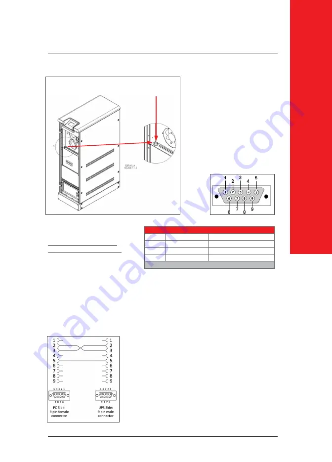
Figure. 8-2
The communication solutions listed below
can be used with this port:
• Monitoring Software (Optional)
• External SNMP Adapter (Optional)
Via SNMP; the information listed below can
be monitored;
• The Latest Battery Test Date
• UPS Information (example: 220V - 50Hz)
• Input Data (V
in
, F
in
, V
max
etc.)
• Output Data (V
out
, Load Percantge...etc.)
• Battery Situation (V
batt
...etc)
8.1.
Serial Communication (RS232)
UPS is equipped with Serial
Communication as standard. RS232
cable shall be shielded and shorter
than 25m.
RS232:
DSUB-9 male connector with
the following pin layout shall be used
on the UPS side of the connection
cable.
RS232 Pin Layout
PIN#
Signal Name
Signal Description
2
TX
Transmit Data
3
RX
Receive Data
5
GND
Signal Ground
Table.8
Communication Cable Path
Over SNMP communication, battery test can be started or current test can be cancelled.
UPS can be shut-down or stand-by (stand-by duration is adjustable). Alarms can be discarded.
If Serial Communication cable is needed, it can be produced according
to the pin c
onfigur
ation described at side.


