26
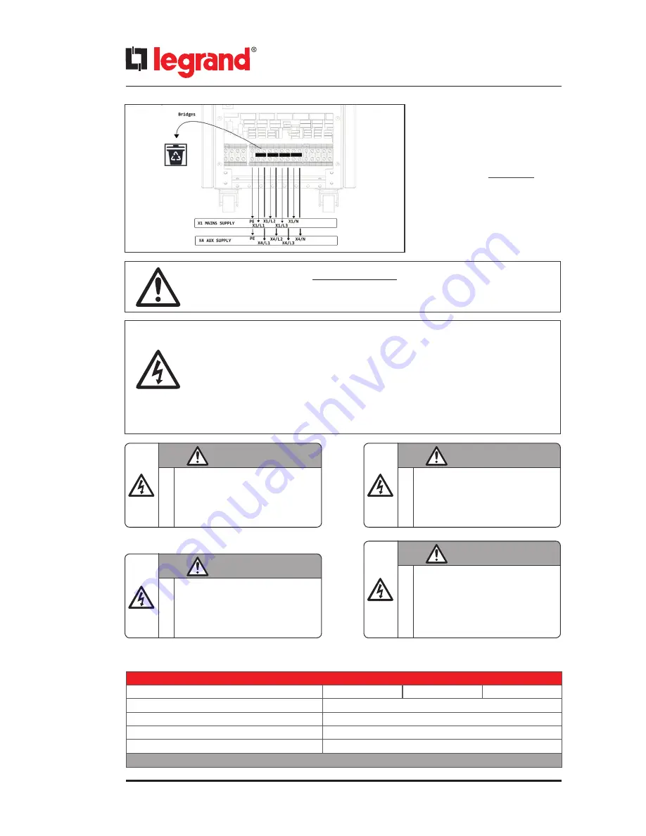
Connect the phase cables to X1
MAINS SUPPLY: X1/L1 - X1/L2 -
X1/L3
terminals, the neutral to X1
MAINS SUPPLY: X1/N
terminal.
Cables must be protected by fuses
or MCCB, refer to Section 5.4
If auxiliary supply exists, remove all bridges.
When used, the residual current
earth leakage protection system must be common for the two AC inputs and in-
stalled upstream.
According to EN 62040-1, the user should place a warning label on the input distribu-
tion panel and the other primary power isolators, in order to prevent the risk of voltage
backfeed.
This label is supplied with the Installation Manual. It indicates:
RISK OF VOLTAGE BACKFEED
• Isolate Uninterruptable Power Supply before working on this circuit.
• Then check for Hazardous Voltage between all terminals including the protective
earth (PE).
WARNING
WARNING
WARNING
EN
IT
FR
RISK OF BACKFEED
BACK FEED RISCHIO
RISQUE DE RETOUR DE TENSION
Before working on this circut
isotale Uninterruptible Power System (UPS),
Then check for hazardous Voltage between
all terminals includig the protective earth
(PE)
Prima di intervenire su questo circuito
isolare I’UPS dalla rete .
Controllare la prensenza di tensioni
pericolose tra tutti i terminali
Avant de travailler sur le circuit électrique
İsoler I’ alimentation sans interruption (ASI)
Puis vérifier s’ il y a présense de tension
dangereuse entre toutes les bornes incluat la
connexion de terre.
WARNING
DE
RÜCKSPANNUNG RISIKO
Bevor Sie einen Eingriff am Grat
vornehmen trennen Sie die USV - Anlage
vom Netz.
Überprüfen Sie auf geharlichte spanunngen
zwischen den Anschlüssen und der
Shutzerde (PE).
..
..
6.3.1.3
.
Auxiliary Supply Connection
Electrical Characteristics - Bypass
Model (kVA)
10
15
20
Bypass frequency slew rate
7 Hz/s
Bypass rated voltage
Nominal output voltage ±18% (settable)
Bypass rated frequency
50/60 Hz (selectable)
Bypass frequency tolerance
±3Hz
Table.5
Summary of Contents for KEOR T EVO
Page 1: ...KEOR T EVO 10 15 20 KVA Installation Operation Manual LE10507AA ...
Page 2: ...LE10507AA KEOR T EVO ...
Page 24: ...22 Figure 6 3 1 3 Figure 6 3 1 4 Power Cables Path Communication Cables Path ...
Page 30: ...28 Figure 6 3 1 4 1 KEOR T EVO 10 1x24pcs 9Ah BATTERY WIRING DIAGRAM ...
Page 32: ...30 Figure 6 3 1 4 3 KEOR T EVO 10 1x24pcs 9Ah BATTERY WIRING DIAGRAM ...
Page 76: ...74 SEPARATED RECTIFIER AND BYPASS INPUTS FOR SINGLE UPS UNIT ...
Page 82: ...Notes ...
Page 83: ......


