56
9.3.
Decommissioning
Follow the order written below to decommission the UPS:
1.
Switch the output circuit breaker on the distribution panel to “
OFF
” position.
2.
Switch the output circuit breaker on the UPS (
Q2
) to “
OFF
” position.
3.
Switch the battery circuit breaker on the UPS (
F5
) to “
OFF
” position.
4.
If exists, switch the circuit breakers on the external battery cabinet to “
OFF
” position.
5.
Switch the mains supply circuit breaker on the distribution panel to “
OFF
” position.
6.
Switch the auxiliary supply circuit breaker on the distribution panel to “
OFF
” position.
7.
Switch the inrush circuit breaker on the UPS (
Q6
) to “
OFF
” position.
8.
Switch the mains supply circuit breaker on the UPS (
Q1
) to “
OFF
” position.
9.
Switch the auxiliary circuit breaker on the UPS (
Q4
) to “
OFF
” position.
Wait a few minutes till UPS completely turn off.
Even without connections on UPS terminals, residual voltages may exist on these
terminals and inside the UPS. Do not touch these parts.
RISK OF BACKFEED:
Before working on UPS terminals, check for Hazardous
Voltage between all terminals including the protective earth (PE).
This procedure may only be executed by trained Personnel.
Some parts inside the UPS including terminals are still energized during maintenance
bypass operation.
All the maintenance operations should be done by authorized LEGRAND UPS
Technical Service Personnel.
During Maintenance Bypass operation; in case any mains voltage interruption occurs,
all loads supplied downstream the UPS will be de-energized. Maintenance Bypass
Operation should not be preferred for long time use.
Maintenance bypass enables the user to isolate the electronic circuitry of the UPS from the mains voltage
and the load without interrupting the load operation by connecting the loads directly to the bypass supply.
This feature is useful while waiting service staff and shall only be executed by trained Personnel.
In order to transfer to Maintenance Bypass without interruption, do the following instruction respectively;
1.
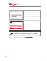
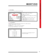
On the display, select
Menu / Command
, enter User password (1111).
2.
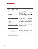
In page
Priority
, select Eco Mode, save and confirm, go back to Energy Flow Diagram screen
3.
Check that UPS is in Eco Mode operation.
4.
Open the front door with the UPS key.
5.
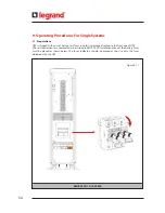
Switch the maintenance bypass circuit breaker on the UPS (
Q3
) to “
ON
” position.
6.
See “
M. Bypass Mode
” written on LCD of UPS.
7.
Switch to “OFF” position the output circuit breaker (
Q2
), the battery circuit breakers (
F5
), the breakers on
external battery cabinets if any, the mains supply circuit breaker (
Q1
) and the inrush circuit breakers (
Q6
)
on the UPS.
8.
Switch the auxiliary supply circuit breaker on the UPS (
Q4
) to “
OFF
” position.
9.
LCD would be off and the alarms would be silenced.
The loads will be continued to be supplied directly from the mains voltage.
9.4.
Maintenance Bypass Commissioning Instructions (Transfer Load Supply from UPS to Internal
Maintenance Bypass)
Summary of Contents for KEOR T EVO
Page 1: ...KEOR T EVO 10 15 20 KVA Installation Operation Manual LE10507AA ...
Page 2: ...LE10507AA KEOR T EVO ...
Page 24: ...22 Figure 6 3 1 3 Figure 6 3 1 4 Power Cables Path Communication Cables Path ...
Page 30: ...28 Figure 6 3 1 4 1 KEOR T EVO 10 1x24pcs 9Ah BATTERY WIRING DIAGRAM ...
Page 32: ...30 Figure 6 3 1 4 3 KEOR T EVO 10 1x24pcs 9Ah BATTERY WIRING DIAGRAM ...
Page 76: ...74 SEPARATED RECTIFIER AND BYPASS INPUTS FOR SINGLE UPS UNIT ...
Page 82: ...Notes ...
Page 83: ......


