background image

62

11.10.

 Maintenance Bypass Active Alarm

If Maintenance Bypass circuit breaker is brought to “ON” position, this alarm appears. Refer to Section 9.5 to 

check if Maintenance Bypass decommissioning procedure has been respected.

11.11.

 Battery test failure Alarm

UPS tests the batteries periodically. In case the batteries failed in the battery test, this alarm appears. 

Perform the test again when the batteries have been charged for min. 10 hours and verify the battery circuit 

breaker is at “ON” position. 
If the alarm continues, contact to Legrand UPS Technical Service. 

11.12.

 Input Voltage Failure Alarms 

If the input voltage is not in specified limits, these alarms appear and In this case UPS operates in Battery 

Operation mode. As soon as the mains voltage returns to specified limits, the alarms will dissappear. 

11.13

. Inverter Temperature High/ Rectifier Temperature High Alarms 

If temperature of the inverter or rectifier block rises, these alarms appear. The reasons can be: overload, fan 

failure, high ambient temperature, and dusty environment. If fans failed or any other problem is identified, 

contact Legrand UPS Technical Service. 
If any other alarm occurs or if the above alarms cannot be cleared, contact Legrand UPS Technical Service. 
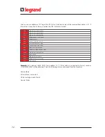
Please prepare the following information before you contact Legrand UPS Technical Service:

• Ensure you read and apply troubleshooting procedure carefully  

• UPS Model Type

• Serial Number

• Firmware version 

• Date of failure or problem

• Date of commissionning

• Symptoms of failure or problem

• Customer site address and contact information

• Service contract references if any

Summary of Contents for KEOR T EVO

Page 1: ...KEOR T EVO 10 15 20 KVA Installation Operation Manual LE10507AA ...

Page 2: ...LE10507AA KEOR T EVO ...

Page 3: ...ntenance Bypass Optional 12 5 REQUIREMENT 13 5 1 Transportation 13 5 2 Placement 13 5 3 Storage 15 5 4 Electrical Requisites 15 6 INSTALLATION 18 6 1 Models and Dimensions 18 6 2 Unpacking Procedure 19 6 3 Installation Procedures and Instructions 20 6 3 1 Power Connections of Single Systems 21 6 3 2 Power Connections of Parallel Systems 34 7 HUMAN MACHINE INTERFACE 36 7 1 Front Panel Segments 36 7...

Page 4: ...ss voltage failure Alarm 61 11 2 Bypass phase sequence wrong Alarm 61 11 3 Inverter not sync with bypass Alarm 61 11 4 Input phase sequence wrong Alarm 61 11 5 Rectifier not sync with input Alarm 61 11 6 DC voltage failure Alarms 61 11 7 ESD active Alarm 61 11 8 Ambient temperature high Alarm 61 11 9 Overload Alarms 61 11 10 Maintenance bypass active Alarm 62 11 11 Battery test failure Alarm 62 11...

Page 5: ...upply a voltage that is perfectly stabilized in frequency and amplitude even in event of extreme alterations of mains power supply The 3 Level Switching Technology used in this product is the latest solution to provide high energy efficiency even with low load conditions The energy efficiency performance of KEOR T EVO surpasses the minimum requirements defined by the Code of Conduct on Energy effi...

Page 6: ...irectives in force at such a date The manual cannot be considered inadequate if updates of standards or changes are made to the equipment Any integration to the manual which the Manufacturer deems fitting to send to the users must be kept with the manual becoming an integral part of it The Manufacturer is available to its clientele to provide additional information and will take into consideration...

Page 7: ... floods etc Unloading and transportation damage and failures after delivery Damage or injuries caused by negligence lack of inspection or maintenance or improper use of the products Faulty electrical wiring Defects arising either from designs or parts imposed or supplied by the purchaser Defects and damage by fire and lightning Failures due to modification in the products without LEGRAND approval ...

Page 8: ...following indications summarize the protective gear to wear 3 1 Description of the Symbols Used on the Labels Applied to the UPS 3 Safety Information related to safety of the UPS battery load and the user is summarized below But the equipment should not be installed before reading the manual completely PE PROTECTIVE EARTH PB PROTECTIVE BONDING DANGER HIGH VOLTAGE BLACK YELLOW This symbol points ou...

Page 9: ... with devices that are suited to the installation the mains voltage surge must be limited to 2kV These protective devices must be sized to take into account all the installation parameters geographical position whether or not there is a lightning rod whether or not there are other suppressors in the electrical installation etc Even when connections removed residual voltages of capacitors and or hi...

Page 10: ... tools or metal parts on top of batteries Eye protection should be worn to prevent injury from accidental electrical arcs Before a maintenance or repair work on the UPS Switch the input output and battery circuit breakers Q1 Q2 and F5 to OFF position If UPS has internal batteries Remove and isolate battery red and N battery neutral blue cables If UPS has external batteries also switch the circuit ...

Page 11: ...he failure conditions and communicates with your computer system UPS can be operated in one of the following operational modes depending on the condition of mains voltage battery load UPS status or user preference You may see the block diagram of UPS in Appendix 6 Description of UPS and Block Diagram 4 1 Online Mode Energy is drawn from the mains voltage input Loads are supplied through the rectif...

Page 12: ... of 1 x 60pcs 12VDC battery with common neutral You may see the battery string connection as below n x 12 18 pcs n x 12 18 pcs POSITIVE STRING NEUTRAL POINT N NEGATIVE STRING Two Serial Strings with Central Point Neutral Potential KEOR T EVO UPS operates with one strings of 24 to 36 x pcs 12VDC battery with common neutral Battery Management and Battery Back Up Time When UPS operates in Online or B...

Page 13: ...put voltage is Ph Ph 400V the tolerance range of bypass voltage would be Ph Ph 328V 472V In case the input voltage decreases below Ph Ph 328V or in creases above Ph Ph 472V if UPS runs in Bypass Mode UPS switches to Online Mode Operation if UPS runs in Online Mode Operation it cannot switch to Bypass Mode Operation even if a fault occurs If the batteries and the inverter are suitable to supply the...

Page 14: ... the mains voltage and the load without interrupting the load operation by connecting the loads directly to the bypass utility supply This feature is useful while performing maintenance or service and should only be executed by trained Personnel Maintenance Bypass enables the user to isolate the electronic circuitry of the UPS from the mains voltage and the load without interrupting the load opera...

Page 15: ...s at the front of the UPS for maintenance Refer to Figure 4 2 4 Air outlets of the UPS are at the front back sides Leave access at the front side back side and from both lateral sides for battery replacement Refer to Figure 5 2 1 5 2 2 5 2 3 and 5 2 4 Recommended environmental humidity condition is between 20 95 non condensing TheUPSmustbeplacedandstandinaverticalpositionthroughoutthetransportatio...

Page 16: ...3 Air conditioning ROOM LAYOUT RECOMMENDATION TABLE for UPS with Internal Battery Ventilation Direction of ventilation is front sides to back The room should be equipped with ventilation system or air conditioning to collect warm air from the top of the room and provide cool air at the bottom ...

Page 17: ... 550 C no receipt of direct sunlight far from the heating in a dry place Environmental humidity must be between 20 95 non condensing Recommended storage temperature humidity and altitude values are listed on the Appendix 1 Technical Specifications section If the batteries will be stored for longer than 6 months they shall be charged periodically Charge period depends on the storage temperature as ...

Page 18: ...g neutral system 20 25 32 Maximum I2t supported by the bypass A2s 10ms 6700 11200 15000 Icc max A 1200 1500 1700 Protection Devices Battery Fast Fuse Ferrule style high speed fuses and with indicating striker High Speed FWP Bussmann Fuse 22x58mm 690VAC IEC A 63 63 63 Recommended Protection Devices Output C curve circuit breaker A 3 or 4 pole according neutral system 3 4 B curve circuit breaker A 3...

Page 19: ...an the recommended size for parallel topologies Must be selective with residual current circuit breakers downstream of the UPS connected to the UPS output If the bypass network is separate from the rectifier circuit or in the event of parallel UPS use a single residual current circuit breaker upstream of the UPS If the loads generates high rate of third harmonic current THDI 33 the current on the ...

Page 20: ...t is also wrapped in a transparent film Check if the following are provided with the equipment Battery fuses three pieces Before the installation please check if your UPS is customized following your special requirements if any 6 1 Models and Dimensions UPS Type Dimension HxWxD mm Net Weight Kg Internal Batteries Type UPS KEOR T EVO 10 KVA 1020H 0 102x26 5x80 78 NO Battery UPS KEOR T EVO 10 KVA 10...

Page 21: ...19 KEOR T EVO Installation Operation Manual Remove the wrap Remove the package Place UPS in the installation area Figure 6 2 1 6 2 Unpacking Procedure Figure 6 2 3 Figure 6 2 2 ...

Page 22: ...densate in it In this case wait minimum for 2 two hours before powering the UPS KEOR TEVOmustbeprotectedfromvoltagesurgewithdevicesthatare suitedto theinstallation the mains voltage surge must be limited to 2kV These protective devices must be sized to take into account all the installation parameters geographical position whether or not there is a lightning rod whether or not there are other supp...

Page 23: ...are located on the lower rear side of the UPS Firstly unscrew the metal cover afterwards remove the cover of terminals After the covers are removed the cables shall be passed through the cable glands and attached under the terminals After all connections done replace the cover 6 3 1 Power Connections of Single Systems Rear view of KEOR T EVO UPS Remove the cover of terminals ...

Page 24: ...22 Figure 6 3 1 3 Figure 6 3 1 4 Power Cables Path Communication Cables Path ...

Page 25: ...1 5 Q1 Common Mains Supply Circuit Breaker Q2 Output Circuit Breaker Q3 Maintenance Bypass Circuit Breaker Q4 Auxiliary Mains Supply Circuit Breaker F5 Battery Fast Fuse Q6 Inrush Circuit Breaker KEOR T EVO 10 15 20kVA 3Ph Input 3Ph Output Circuit Breakers ...

Page 26: ...T PB N PE X2 L1 X2 L2 X2 L3 X2 N KEOR T EVO 10 15 20kVA 3Ph Input 3Ph Output Connection if the MAINS and AUX Supply are connected in COMMON Figure 6 3 1 6 X1 MAINS SUPPLY X4 AUX SUPPLY PE X1 L1 X1 L2 X1 L3 X1 N X4 L1 X4 L2 X4 L3 X4 N ...

Page 27: ...ce connection As the Auxiliary Supply Protective Bonding PB and Input Mains Supply s Protective Earth PE terminals are short circuited inside UPS it is not needed any connection Load ground should be connected to output X2 PB terminal of the UPS If there is an external battery cabinet present it should be grounded via battery X5 PB terminal of the UPS Electrical Characteristics Rectifier Input Mod...

Page 28: ...R RISK OF BACKFEED BACK FEED RISCHIO RISQUE DE RETOUR DE TENSION Before working on this circut isotale Uninterruptible Power System UPS Then check for hazardous Voltage between all terminals includig the protective earth PE Prima di intervenire su questo circuito isolare I UPS dalla rete Controllare la prensenza di tensioni pericolose tra tutti i terminali Avant de travailler sur le circuit électr...

Page 29: ...ables Connect the unconnected battery cables to the related battery connectors The unconnected cables are labelled You may find detailed information about battery connection as follows There is no need for any further connection so reconnect the side panels earth cables and replace the covers Danger of explosion and fire if the batteries of the wrong type are used Battery fast fuses shall only be ...

Page 30: ...28 Figure 6 3 1 4 1 KEOR T EVO 10 1x24pcs 9Ah BATTERY WIRING DIAGRAM ...

Page 31: ...29 KEOR T EVO Installation Operation Manual Figure 6 3 1 4 2 KEOR T EVO 10 1x24pcs 9Ah BATTERY WIRING DIAGRAM ...

Page 32: ...30 Figure 6 3 1 4 3 KEOR T EVO 10 1x24pcs 9Ah BATTERY WIRING DIAGRAM ...

Page 33: ...t 1 to X5 EXT BATTERY on the UPS Connect the on Battery Cabinet 2 to X5 EXT BATTERY on the Battery Cabinet 1 and so on Neutral Connect the N on Battery Cabinet 1 to X5 EXT BATTERY N on the UPS Connect the N on Battery Cabinet 2 to X5 EXT BATTERY N on the Battery Cabinet 1 and so on External Battery CabinetTemperature Sensor Only connect the X7 X7 1 X7 2 X7 3 on the Battery Cabinet 1 to X7 X102 1 X...

Page 34: ...32 Unplug the cable of Thermal Sensor Board on the UPS Power Connection of Single Battery Cabinet Signal Connection of Single Battery Cabinet Figure 6 3 1 4 8 Figure 6 3 1 4 7 ...

Page 35: ...sary to modify the neutral Connect the phase cable to X2 OUTPUT X2 L1 X2 L2 X2 L3 terminal and the neutral cable to X2 OUTPUT X2 N terminal Cables must be protected by fuses or MCCB refer to Section 5 4 Electrical Characteristics Inverter Model kVA 10 15 20 Rated output voltage selectable V 400 3Ph N PB 380 415 configurable Output voltage tolerance static load 1 dynamic load VF SS 111 compliant Ra...

Page 36: ...ined in Section 5 4 considering total parallel UPS power Please check 6 3 1 Power Connections of Single Systems for detailed connection information The cross section and length of the input and output cables must be identical for all units The phase rotation must be the same for each unit connected in parallel and also on any external manual bypass line Make sure that electrical connections and th...

Page 37: ...35 KEOR T EVO Installation Operation Manual Figure 6 3 2 1 CANBUS CONNECTION OF TWO PARALLEL UPS CANBUS CONNECTION OF THREE AND UP TO MAXIMUM 4 UNITS IN PARALLEL Figure 6 3 2 2 ...

Page 38: ...an Machine Interface Energy Flow Diagrams Menus Alarms Measurements Settings Diagnostics About Commands Output Power Output Battery DC Bypass Rectifier Diagnostics Events Details Piriortiy Battery Test Authorizations RelayFuntions Options EventLogs FrequencyConvertor OutputVoltage OutputFrequency BypassVoltageRange Battery1 2 Battery2 2 BatteryChargeCurrent AutoBatteryTest ParallelMode EmergencyPo...

Page 39: ...PS s current operation mode Load Shows the percentage of the load as numerical and graphical information If there is overload at the output the load graphic lits Red You may reach the output power measurements by touching it Menu You may reach the menus by touching it Configuration It indicates if UPS is in parallel or single operation configuration In Single Mode there is no symbol Time It indica...

Page 40: ...38 Operation Modes of UPS and Energy Flow Diagram Online Mode Frequency Converter Mode Battery Mode Bypass Mode Bypass Line is Orange ...

Page 41: ... 1 2 UPS Status LED Bar Status LED Bar under the front panel gives information of current UPS status No Operation You may see the colour code assigned for status of UPS GREEN Everything is OK on UPS Load is protected ORANGE The load is supplied by UPS but an alarm is active control is required RED The load is not supplied by UPS Emergency exists ...

Page 42: ... check Appendix 1 Alarms List You may reach sub menus by touching Menu Alarms Measurements Settings Diagnostics About and Commands All active alarms present are displayed on the Alarms screen They will appear in red colour and as soon as acknowledged by touching the hand icon at the right side of the screen they switch to gray colour and the buzzer will stop In case a new alarm occurs the buzzer i...

Page 43: ...ENTS menu are as below Output load percentage apparent power real power and power factor information of each phase is displayed Output voltage Ph N current frequency information of each phase is displayed DC Bus and Positive Negative string of battery voltage is displayed When the battery circuit breaker is closed it gives just Battery Voltage measurements Charge Discharge battery current ambient ...

Page 44: ...mation of each phase are displayed If the MAINS and AUX Supply are connected in COMMON Rectifier and Bypass values will be the same When the Password Screen appears enter 1111 touch ENTER to confirm 7 2 3 Settings Menu This menu is the section where all the settings related to UPS usage customization can be done User Password must be entered to make changes in this section User Password 1111 the p...

Page 45: ...isabled if requested You can adjust brightness setting of LCD screen When you touch the save icon key a confirmation pop up bar will appear You should touch Yes to save the settings Touch No to exit without saving the changes You may choose communication options here If Modbus is chosen you may also make Modbus adjustments There are 4 different relays and one alarm is assigned to each relay ...

Page 46: ...nges UPS records the event logs with the date and time information Thus the events can be followed chronologically When you touch the save icon key a confirmation pop up bar will appear You should touch Yes to save the settings Touch No to exit without saving the changes UPS records the event logs with the date and time information Thus the events can be followed chronologically When you touch the...

Page 47: ...ettings Touch No to exit without saving the changes You may see UPS status here There are 17 different notifications When you touch the calendar icon you may reach below Event Menu 7 2 4 Diagnostics Menu All the alarms notifications are logged real time and can be reached via this menu UPS displays up to 380 last events Events are stored in EEPROM using FIFO method Order number of last occurred ev...

Page 48: ...ils of it as you see on the side You may see the details of the event with event code If Technical Support required taking notes of current event logs would be useful You may reach detailed information about events from Appendix 3 Event List 03 01 2012 21 23 Back Event descripton Flags Rectifier reception timeout 0x2940 0x15F0 0xe628 0x0322 Details Online ...

Page 49: ...ges in this section User Password 1111 the password cannot be changed You may see the COMMAND Menu s screen as below UPS UPS model and nominal power Serial UPS serial number UPS output UPS output voltage Ph N Ph Ph and frequency HMI version Human Machine Interface version Inverter version Inverter firmware version Rectifier version Rectifier firmware version When the Password Screen appears enter ...

Page 50: ... system is configured as Parallel you may choose operation mode of UPS Online or Bypass Mode It would be enough to set the priority on one of the UPS all the UPSs will pass to Bypass Mode at the same time When you touch the Save icon key a confirmation pop up bar will appear You should touch Yes to save the settings Touch No to exit without saving the changes With this command UPS battery test fea...

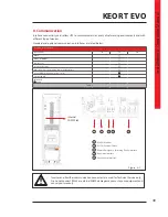
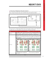
Page 51: ...BUS Dry Contacts Generator Interface Remote Emergency Switching Device ESD Interface Internal SNMP Web Monitoring e mail External SNMP Standard Option Table 2 Inverter and Rectifier communication connectors are used for Technical Service only Do no not connect RS232 or external SNMP damage may occur to your equipment and cancel your warranty 1 RS485 Modbus 2 RS232 External SNMP 3 Remote Emergency ...

Page 52: ...unication as standard RS232 cable shall be shielded and shorter than 25m RS232 DSUB 9 male connector with the following pin layout shall be used on the UPS side of the connection cable RS232 Pin Layout PIN Signal Name Signal Description 2 RX Receive Data 3 TX Transmit Data 5 GND Signal Ground Table 8 Communication Cable Path Over SNMP communication battery test can be started or current test can b...

Page 53: ... Generator contact is Normally open UPS OFF If the UPS OFF EPO input set by an EPO switch UPS stops generating the output voltage and stops feeding the load When the voltage on the digital input is removed you have to restart UPS The factory default setting of ESD contact is Normally open Table 9 8 2 Emergency Switching Device and Generator Connections UPS can be remotely switched off and can be c...

Page 54: ...Maximum contact current depends on the applied voltage and the load characteristic Both maximum voltage and maximum contact current corresponding to the applied voltage shall not be exceeded Free contact relay connection cables shall have a cross section of 1 5 mm2 Maximum allowed resistive contact currents for several voltages are given on the table below Each relay has both a normally open NO an...

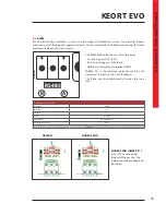
Page 55: ...potential used by the transceiver to measure the A and B voltages The B line is positive compared to A when the line is idle 8 4 RS485 RS485 with Modbus protocol is used in a wide range of automation systems for Industrial Process monitoring or for Building Management Systems This communication link allows monitoring UPS status and measurements with such systems RS485 RS485 A B Communication Param...

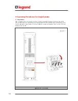
Page 56: ... in a plastic package attached to the front side of UPS After all connections are completed as described in KEOR T EVO Installation Manual the battery fuses must be placed as shown below The fuses indicators should be placed at top Use only the fuses delivered with the UPS Figure 9 1 1 KEOR T EVO 10 15 20KVA ...

Page 57: ...ecircuitbreakeryet 2 Switch the auxiliary supply circuit breaker on the distribution panel to ON position 3 Switch the mains supply circuit breaker on the distribution panel to ON position 4 Switch the auxiliary supply circuit breaker on the UPS Q4 to ON position 5 Switch the mains supply circuit breaker on the UPS Q1 to ON position 6 Switch the inrush circuit breaker on the UPS Q6 to ON position ...

Page 58: ...ersonnel During Maintenance Bypass operation in case any mains voltage interruption occurs all loads supplied downstream the UPS will be de energized Maintenance Bypass Operation should not be preferred for long time use Maintenance bypass enables the user to isolate the electronic circuitry of the UPS from the mains voltage and the load without interrupting the load operation by connecting the lo...

Page 59: ... Bypass Mode written on LCD of UPS 5 Switch the circuit breakers on the external battery cabinet to ON position 6 Touch Battery icon to see Battery DC menu measurement Do not close the battery circuit breakers F5 until the DC bus reaches 372V 7 Switch the output circuit breaker on the UPS Q2 to ON position 8 Switch the maintenance bypass circuit breaker on the UPS Q3 to OFF position 9 Check on Ene...

Page 60: ...or maintenance operation without affecting the load supply by the remaining operating UPS units N 1 redundancy means than one UPS unit can be stopped without affecting secured load supply N 2 redundancy means than up to two UPS unit can be stopped without affecting secured load supply Maximum Load per parallel UPS unit to keep redundancy Parallel configuration must only be activated by LEGRAND UPS...

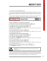
Page 61: ...ch Start up for PARALLEL UPSs on Maintenance Bypass Mode 1 Switch Q4 Auxiliary Supply circuit breakers of all UPSs ON position 2 Switch Q1 Mains Supply circuit breakers of all UPSs to ON position 3 Switch Q6 Inrush circuit breakers of all UPSs to ON position 4 LCDs will be ON See M Bypass Mode written on LCD of all UPS 5 Touch Battery icon to see Battery DC menu measurement Do not close the batter...

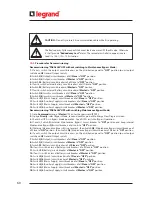
Page 62: ...ance Bypass Mode 1 Go to Commands menu of Master UPS enter User password 1111 2 In page Priority select Bypass Mode save and confirm go back to Energy Flow Diagram screen 3 Check that UPS is in Bypass Mode operation See all UPSs switch to Bypass Operation 4 If exists Switch Q External Maintenance Bypass circuit breaker to ON position and keep internal Maintenance Bypass Q3 circuit breakers of all ...

Page 63: ... rectifier or common mains supply voltage is out of limit Check if common mains supply is in specified limits 11 6 Dc Voltage Failure Alarms Any of the DC bus voltages is out of the limit If you encounter this alarm during start up check if the inrush circuit breaker is at ON position Check polarity of external battery connections if any If it still exists contact the LEGRAND Technical Assistance ...

Page 64: ...in Battery Operation mode As soon as the mains voltage returns to specified limits the alarms will dissappear 11 13 Inverter Temperature High Rectifier Temperature High Alarms If temperature of the inverter or rectifier block rises these alarms appear The reasons can be overload fan failure high ambient temperature and dusty environment If fans failed or any other problem is identified contact Leg...

Page 65: ...nd chemical hazard lethal voltage present When replacing batteries the same quantity and type that were originally fitted should be used Batteries must always be disposed of according to local environmental laws Preventive Maintenance includes extended control of all the electronic and mechanical components in UPS and permits to replace components before their end of life to assure optimum availab...

Page 66: ...aintenance and replacement before end of life shall be done by authorized LEGRAND UPS Technical Service Personnel periodically 12 4 Capacitors The life of the DC electrolytic capacitors and AC filter capacitors used for output and input filtering purposes depends on the UPS usage and environmental conditions Preventive maintenance and replacement before end of life shall be done by authorized LEGR...

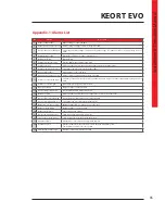
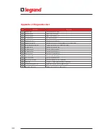
Page 67: ...quency range of rectifier or input mains voltage is out of limit 12 Rectifier not precharged DC voltage not charged by inrush circuit 13 DC voltage failure DC Bus voltage is out of the limit 14 Inverter temperature high Inverter IGBT module temperature high 15 Output overload RMS current drawn from any of the output lines exceeds its nominal value 16 Inverter DC component high Inverter voltage s D...

Page 68: ...temperature exceeds the upper limit 8 Rectifier passive Rectifier is not running now 9 Rectifier blocked Rectifier is blocked by UPS 10 Rectifier disabled Rectifier is disabled by user 11 Inverter passive Inverter is not running now 12 Inverter blocked Inverter is blocked by UPS 13 Inverter disabled Inverter is disabled by user 14 Generator mode active Generator friendly operation is activated 15 ...

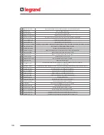
Page 69: ... circuit breaker is at I position 20 Batt test completed Battery test is completed 21 Redundancy ok All parallel UPS are OK 22 N number ok All parallel UPS are OK 23 Rectifier enabled Rectifier enabled is set as YES from front panel 24 Inverter enabled Inverter enabled is set as YES from front panel 25 Bypass enabled Bypass enabled is set as YES from front panel 26 Eco mode passive Eco Mode enable...

Page 70: ...utput breaker open Output Circuit Breaker is at OFF position 57 Batt test active Battery test is on progress 58 Redundancy lost Parallel system alarm The total load is more than the redundancy load The formula is Load N N 1 100 59 N number failure Parallel system alarm If the UPS number in parallel is less than the preadjusted N number that alarm appears 60 Rectifier disabled Rectifier enabled is ...

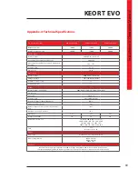
Page 71: ... PB 380 415 Adjustable Power Factor 1 Wave Form Sinusoidal Frequency Hz 50 or 60 Adjustable Frequency Tolerance Battery Operation 0 01 Voltage Regulation Static 1 Output voltage unbalance at reference unbalance load 0 5 Maximum phase angle variation 0 1 Crest Factor 2 4 1 2 6 1 2 4 1 Nominal Power kVA 10 15 20 Overload Protection sec 10 15KVA 600 100 125 Load 20KVA 480 100 125 Load 30 C 10 15KVA 6...

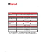
Page 72: ...ic Noise dBA 52 53 55 Pyhsical Dimensions HxWxD mm 1020 x 265 x 800 Weight kg without battery transformer 78 79 84 Paint RAL 7016 enclosure RAL 9005 front door metal Standards Safety IEC EN 62040 1 EMC IEC EN 62040 2 Performance IEC EN 62040 3 Design IEC EN 62040 ISO 9001 2008 ISO 14001 2004 Protection IP 20 other IP as option Please contact Legrand or your local authorized distributor for optiona...

Page 73: ...oltage R 108 1 L2 Output Voltage R 109 1 L3 Output Voltage R 110 1 L1 Output Current R 111 1 L2 Output Current R 112 1 L3 Output Current R 113 0 1 Output Frequency R 114 1 L1 Output Load Percentage R 115 1 L2 Output Load Percentage R 116 1 L3 Output Load Percentage R 117 1 L1 Bypass Voltage R 118 1 L2 Bypass Voltage R 119 1 L3 Bypass Voltage R 120 1 Positive Battery String Voltage R 121 1 Negative...

Page 74: ...0001 will be obtained Then the following status can be read from that number bit 0 UPS operates on Online Mode bit 1 UPS operates on Bypass Mode bit 2 UPS operates on Battery Mode bit 3 Output voltage is out of limits bit 4 Output overload bit 5 Inverter temperature is high bit 6 Rectifier temperature is high bit 7 Ambient temperature is high bit 8 Bypass is not synchronized bit 9 Maintenance Bypa...

Page 75: ...tor X1 Common Mains Supply Terminals X2 Output Terminals X4 Auxiliary Mains Supply Terminals BYPASS THYRISTOR In case any inverter fault occurs Bypass thyristors transfer the supply of the load electronically from inverter to Auxiliary Mains Supply without any interruption RECTIFIER The rectifier generates a very constant DC voltage level by drawing current from the input with a power factor close...

Page 76: ...74 SEPARATED RECTIFIER AND BYPASS INPUTS FOR SINGLE UPS UNIT ...

Page 77: ...75 KEOR T EVO Installation Operation Manual COMMON RECTIFIER AND BYPASS INPUTS FOR SINGLE UPS UNIT ...

Page 78: ...Q3 Internal Maintenance Bypass can be used when total load single unit rating kVA Option o1 o2 unit output disconnect switch to enable single unit complete shut down for maintenance a b o should be 4poles unless TN C distribution is used In case we have parallel system with internal transformer it is recommended to install output switches o to enable sequential energizing of the different ...

Page 79: ... Q3 Internal Maintenance Bypass can be used when total load single unit rating kVA Option o1 o2 unit output disconnect switch to enable single unit complete shut down for maintenance a o should be 4poles unless TN C distribution is used In case we have parallel system with internal transformer it is recommended to install output switches o to enable sequential energizing of the different transform...

Page 80: ...tenance Bypass MCCB OS general output disconnect switch Rating N X unit rating kVA Internal Maintenance Bypass Q3 cannot be used should be locked to avoid any misuse Option o1 o2 o3 unitoutputdisconnectswitchtoenablesingleunitcompleteshutdownformaintenance a b o OS Q should be 4poles unless TN C distribution is used In case we have parallel system with internal transformer it is recommended to ins...

Page 81: ... Maintenance By pass MCCB OS general output disconnect switch Rating N X unit rating kVA Internal Maintenance Bypass Q3 cannot be used should be locked to avoid any misuse Option o1 o2 o3 unitoutputdisconnectswitchtoenablesingleunitcompleteshutdownformaintenance a o OS Q should be 4poles unless TN C distribution is used In case we have parallel system with internal transformer it is recommended to...

Page 82: ...Notes ...

Page 83: ......

Page 84: ... LIMOGES CEDEX Freance 33 5 55 06 87 87 Fax 33 5 55 06 74 55 www legrandelectric com Legrand reserves at any time the right to modify the contents of this booklet and to communicate in any form and modality the changes brought to tehe same Installer Stamp ...

Reviews: