65
KEOR T EVO
Installa
tion & Oper
ation M
anual
No
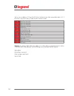
Alarms
Description
1
Bypass voltage failure
Bypass voltage is out of the limit
2
Bypass phase sequence wrong
Phase sequence of bypass mains voltage is not OK
3
Inverter not sync. with bypass
Frequency of bypass voltage is beyond the frequency range for online operation or bypass voltage is out of
limit.
4
Battery breaker open
Battery fuses blown or breaker opened by user
5
Battery test failure
Battery failure
6
Rectifier temperature high
Rectifier IGBT module temperature high
7
Rectifier overload
RMS current drawn from any of the input lines exceeds its nominal value.
8
Rectifier communication lost
Front panel can not communicate with rectifier
9
Input voltage failure
Input voltage is out of the limit
10
Input phase sequence wrong
Phase sequence of input mains voltage is not OK
11
Rectifier not sync. with input
Frequency of input mains voltage is beyond the frequency range of rectifier or input mains voltage is out of
limit.
12
Rectifier not precharged
DC voltage not charged by inrush circuit
13
DC voltage failure
DC Bus voltage is out of the limit
14
Inverter temperature high
Inverter IGBT module temperature high
15
Output overload
RMS current drawn from any of the output lines exceeds its nominal value.
16
Inverter DC component high
Inverter voltage’s DC component is out of the limit
17
Inverter communication lost
Front panel can not communicate with inverter
18
Output DC component high
Output voltage’s DC component is out of the limit
19
Output voltage failure
Output voltage is out of the limit
20
Output short circuit
Short circuit at the output
21
Master communication lost
Slave cannot communicate with master
22
Slave not sync. with master
Slave lost the synchronization with the master
23
N number failure
Parallel UPS count is below the adjusted N number
24
Redundancy lost
Parallel system alarm. The total load is more than the redundancy load.
The formula is : Load % > N / (N+1) * 100
25
Ambient temperature high
Maximal ambient temperature reached
Appendix-1: Alarms List
Summary of Contents for KEOR T EVO
Page 1: ...KEOR T EVO 10 15 20 KVA Installation Operation Manual LE10507AA ...
Page 2: ...LE10507AA KEOR T EVO ...
Page 24: ...22 Figure 6 3 1 3 Figure 6 3 1 4 Power Cables Path Communication Cables Path ...
Page 30: ...28 Figure 6 3 1 4 1 KEOR T EVO 10 1x24pcs 9Ah BATTERY WIRING DIAGRAM ...
Page 32: ...30 Figure 6 3 1 4 3 KEOR T EVO 10 1x24pcs 9Ah BATTERY WIRING DIAGRAM ...
Page 76: ...74 SEPARATED RECTIFIER AND BYPASS INPUTS FOR SINGLE UPS UNIT ...
Page 82: ...Notes ...
Page 83: ......

