77
KEOR T EVO
Installa
tion & Oper
ation M
anual
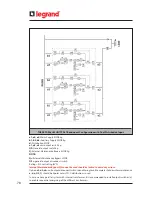
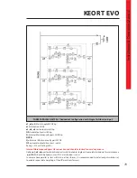
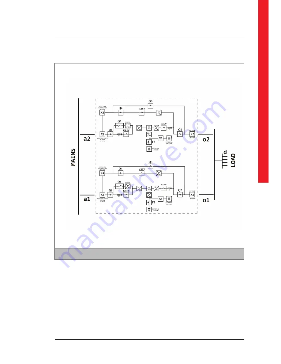
TWO PARALLEL UNITS 1+1 Redundant Configuration with Single Distribution Input
a1, a2:
Mains Supply MCCB 4p
d:
Distribution MCCB
o1, o2,
unit output switch 4p
NOTE :
Q3=
Internal Maintenance Bypass can be used when total load < single unit rating (kVA)
Option o1, o2= unit output disconnect switch to enable single unit complete shut down for maintenance
a, o should be 4poles unless TN-C distribution is used
In case we have parallel system with internal transformer; it is recommended to install output switches (o)
to enable sequential energizing of the different transformers.
Summary of Contents for KEOR T EVO
Page 1: ...KEOR T EVO 10 15 20 KVA Installation Operation Manual LE10507AA ...
Page 2: ...LE10507AA KEOR T EVO ...
Page 24: ...22 Figure 6 3 1 3 Figure 6 3 1 4 Power Cables Path Communication Cables Path ...
Page 30: ...28 Figure 6 3 1 4 1 KEOR T EVO 10 1x24pcs 9Ah BATTERY WIRING DIAGRAM ...
Page 32: ...30 Figure 6 3 1 4 3 KEOR T EVO 10 1x24pcs 9Ah BATTERY WIRING DIAGRAM ...
Page 76: ...74 SEPARATED RECTIFIER AND BYPASS INPUTS FOR SINGLE UPS UNIT ...
Page 82: ...Notes ...
Page 83: ......

