Page 12
INSTALLING THE VERTICAL LEVER LOCK KIT (IF PURCHASED)
NOTE
:
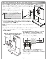
• One 10” Lever Lock plate (F), bracket (G), (2x) screws (H), (6x)
securing rivets (J), and (20x) washers (K) are provided
with a Vertical Lever Lock kit, if purchased.
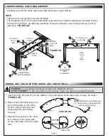
• The 4 available mounting locations on the left and right columns
of the display stand’s small device storage area are for vertical
Lever Lock and are shaded in the figure for clarity.
(
FIGURE H
)
• Lever Lock brackets and plates may be installed to face the
front or the back of the display stand.
• Adjust torque on power driver to lightest setting and only increase
as necessary.
1. Use power driver, Phillips bit and (2x) 10-32 x ⅜” thread forming
screws (H) to attach brackets (G) into one of the 4 positions along
the left and right columns on your display stand as shown.
(
FIGURE J
)
NOTE
: Figure J shows 2 vertical Lever Lock brackets (each kit
sold separately) installed in the lower sides of the display stand
for clarity.
3. Insert securing rivets (J) on the tab beneath the clip of the 10” plate to lock it in place.
NOTE
: Use (20x) washers (K) for equipment mounting convenience.
2. Attach the 10” Lever Lock
plate (F) by inserting the side
with the 2 tabs and no
securing clip first.
Insert the tabs into the
corresponding openings on
the bracket or the display
stand.
Then, install the side with the
clip. See Figure G on page 11
for more information.
(
FIGURE G
)
1
2
3
4
NOTE
: Bare frame of display stand
(free-standing pictured) shown for clarity.
10” Lever
Lock
Plate
NOTE
:
Pre-installed
inside center
column of
display
stand.
FIGURE H
Use (2x) screws (H) to install
bracket (G) with the flanges
in your desired direction.
NOTE
: The
second screw
is not visible
from this figure,
however, the
installation is
the same as
the one shown.
FIGURE J
H
G
NOTE
: The figure shows 2
vertical Lever Lock brackets
(each kit sold separately) in the
lower side positions of the
display stand for clarity.


