Page 13
USING TOP SMALL DEVICE STORAGE AND BOTTOM RACKMOUNT BAYS
NOTE
:
• Each bottom rackmount bay on all display stand models includes 2RU fixed rackrail pairs for device
storage that may be re-positioned in 7 vertical 1.5” (38mm) increments.
• Adjust torque on power driver to lightest setting and only increase as necessary.
4. Use power driver and a 5/16” socket to remove the 10-32 nuts, re-position the brackets to the same
height, and re-install the nuts as necessary.
5. Attach devices to the rackrail using a #2 screwdriver and your own rack screws.
NOTE
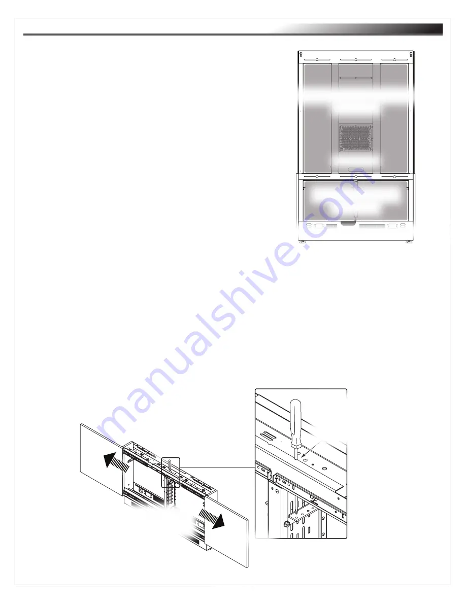
: If using the rackrails in higher bay positions, attach your rack screws using your screwdriver
through the obrounds on the frame as shown.
(Shaded for Clarity)
FIGURE K
(Shaded for Clarity)
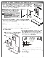
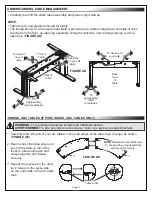
Top Small Device Storage Columns
Bottom Rackmount Bays
NOTE
: Bare frame of display stand shown for clarity.
1. Load equipment into the top small device storage columns
using
“Installing and Configuring the 10” Lever Lock Plate” on
page 11 and “Installing the Lever Lock Kit (If Purchased) on
page 12 as needed. (
FIGURE K
)
2. Run cabling using knockouts between the top small device
storage columns and the bottom rackmount bays as
necessary.
FLOOR-TO-WALL DISPLAY STANDS ONLY
: You must load
any components into the top small device storage columns and
the bottom rackmount bays at this point in the overall installation
and configuration process because you won’t have access to
these areas after re-installing the front panel and mounting your
display.
3. Carefully push outward on the front doors covering
the bottom rackmount bays to open them and load
NOTE
: Top small device
storage columns removed
for clarity.
Carefully push
outward on front doors
to slide them open.
Use #2 screwdriver
through obrounds on
the frame to access
rackrail from higher
positions.
FIGURE L


