Page 14
USING TOP SMALL DEVICE STORAGE AND BOTTOM RACKMOUNT BAYS (CONTINUED)
RE-ATTACHING THE FRONT PANEL TO YOUR DISPLAY STAND
• Carefully re-install both the front panel and the front filler panel by reversing the steps in “Removing the
Front Panel from Your Display Stand” on page 8.
NOTE
:
• If indentations have formed on the acoustic felt (PET) material of panels during re-attachment, apply
steam to remove.
• Clean dust and debris from panels with a clean, soft, lint-free cloth or vacuum.
• Bleach and cleaning agents are not recommended, as they may discolor the material.
FLOOR-TO-WALL DISPLAY STANDS ONLY
:
• Access to the bottom rackmount bays is only available from the the front doors after re-installing the
front panel and mounting your display.
• The useable equipment depth of the bottom rackmount bays in a floor-to-wall display stand is
16” (423mm).
FREE STANDING DISPLAY STANDS ONLY
:
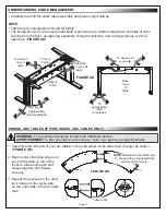
• E
quipment may be loaded into either
the top small device storage columns
and into the bottom rackmount bays at
any point during the overall installation
and configuration process. In addition
to front door access to the bottom
rackmount bays, you can also access
both the top small device storage and
bottom rackmount bays from the back by
carefully tugging at the magnetic sides of the
back panel and opening back bay latch
panels, respectively.
(
FIGURE M
)
• The useable equipment depth of the
bottom rackmount bays in a free standing
display stand is 12” (329mm).
FIGURE M
NOTE
: Back panel and back bay
latch panels (only on free standing
models) shown in black for clarity.
Back Panel
Back Bay Latch
Panels
FIGURE N
1. Use a toothpick or small straw as a thread depth indicator and
insert it into a threaded insert on the back of your display.
2. With the toothpick or straw fully inserted, use a pencil to mark
it at ⅛” above the surface as shown. (
FIGURE N
)
Mark
⅛”
Above Depth
Thread Depth
Indicator
(Toothpick or Straw)
NOTE
:
The interface hardware kit provided includes different pan head screws (I-A) to accommodate
the threaded inserts on the back of most displays. This topic helps you select the correct size pan head
screw length for your display.
SELECTING THE CORRECT INTERFACE BRACKET HARDWARE FOR YOUR DISPLAY


