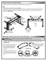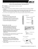
SELECTING CORRECT INTERFACE BRACKET HARDWARE FOR DISPLAY (CONTINUED)
CAUTION
: Only use screws shorter than the ⅛” mark or
damage to the display may occur.
ATTENTION
: N'utilisez que des vis plus courtes que la
marque ⅛” ou vous risquez d'endommager l'écran.
3. Select a pan head screw (I-A) size that is shorter in length than the
⅛” mark you made on your thread depth indicator. (
FIGURE P
)
• The
hardware used
must be assembled in the
arranged order shown in this topic.
• A minimum of 2 pan head screws, washers, and spacers (if spacers
required) must be used on each interface bracket.
NOTE
:
• Spacers must be used if your display has recessed and/or
uneven portions on the back where the threaded
inserts are located. Even if that is not
the case, you may still prefer the
added depth the spacers
provide.
NOTE
:
You may need to install any additional accessories you may have purchased such as
compatible camera mounts, sound bars and other audio products (available from Legrand or other
providers) before your display mount and display. Before proceeding, refer to the instructions provided
with your accessory for the proper installation order.
1. Carefully place your display facedown onto an appropriate work surface.
NOTE
: Center the interface brackets (I-B) on your display so they do not extend past the top or bottom.
2. Determine the correct size pan head screws for attaching the interface brackets to your display. For
more information, see the previous topic.
3. Determine if spacers (I-C) are required when attaching the interface brackets to the back of your
display.
NOTE
: Adjust torque on power driver to lightest setting and only increase as necessary.
4. Use a power driver, #2 Phillips bit, (4x) spacers (I-C, if required), (4x) washers (I-D), and (4x) correct
length pan head screws to attach the interface brackets to the back of your display as shown.
(
FIGURE J
)
ATTACHING INTERFACE BRACKETS TO THE BACK OF YOUR DISPLAY
I-B
I-D
Mounting
Screws
I-C
Depth
Plus
⅛”
Allowance
Mark
Thread Depth
Indicator
(Toothpick or Straw)
I-A
FIGURE P
FIGURE R
Page 15


