Page 16
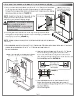
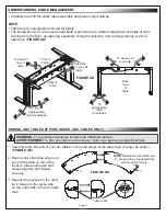
2. Carefully thread the bolt heads on the top 2 loosely attached bolts
through the corresponding keyholes on the shroud (N), and then the
mount (I-E) as shown.
(
FIGURE T
)
NOTE
: Adjust torque on power driver to lightest setting and only increase as
necessary.
3. Use adjustable wrench on the top 5/16-18” flange nuts (M) while using power driver and
½” socket to
tighten the corresponding
5/16-18” x 1¾” flange hex head bolts (L).
Do not overtighten.
5. Use adjustable wrench on both bottom 5/16-18”
flange nuts (M) while using power driver and
½”
socket to tighten corresponding
5/16-18” x 1¾” flange
hex head bolts (L).
Do not overtighten.
4. Use your hand to thread (2x) 5/16-18” x 1¾” flange
hex head bolts (L) through the obrounds on the
lower side of the bottom 2 keyholes on the mount
(I-E), through corresponding holes on the shroud, and
into the display mount. (
FIGURE U
)
1. Use your hand to loosely attach (2x) 5/16-18” x 1¾” flange hex head bolts
(L) to (2x) 5/16-18” flange nuts (M, approximately 2-3 thread rotations)
through the front panel and into your chosen top 2 locations on the display
stand assembly as shown.
(
FIGURE S
)
NOTE
: Select from the top 10 hole pairs on the
display mount for the top bolts and nuts to
determine your preferred display height.
ATTACHING THE SHROUD AND MOUNT TO YOUR DISPLAY STAND
FIGURE S
L
Front Panel
Display
Stand
M
WARNING:
This procedure requires at
least one additional person.
AVERTISSEMENT:
Cette procédure
nécessite au moins une personne
supplémentaire.
I-E
FIGURE U
Holes align with
the obrounds on
the lower side of
the keyholes.
NOTE
: Top 2 hex bolts (L) and keyholes on shroud
(N) and mount (I-E) shown in black for clarity.
L
Top 2
Keyholes
on Shroud
Top 2
Keyholes
on Mount
I-E
N
FIGURE T
A
NOTE
: Select from top
10 hole pairs (shaded) for
preferred display height.


