Page 20
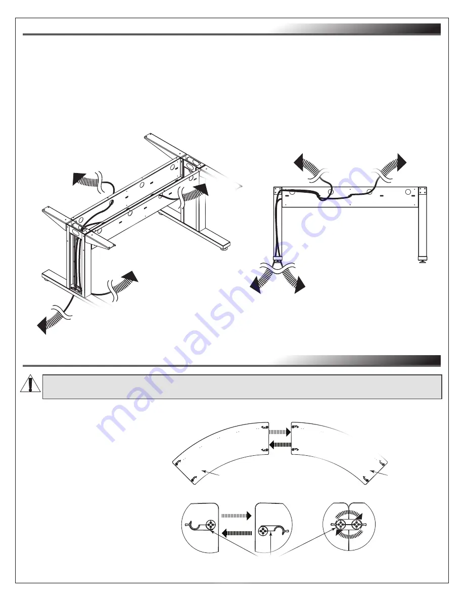
UNDERSTANDING CABLE MANAGEMENT
• Carefully team lift the entire table assembly and place it right-side up.
NOTE
:
• Table top (V) and panels removed for clarity.
• The image shown of a 3 person angle table is provided as a cable management example of lines
coming from the floor, up table leg assembly, through knockouts, tied to bridge lances, and out
openings.
(
FIGURE AD
)
JOINING
ARC TABLES (IF PURCHASED, ARC TABLES ONLY)
WARNING:
This procedure requires at least one additional person.
AVERTISSEMENT:
Cette procédure nécessite au moins une personne supplémentaire.
NOTE
: Underside of arc table tops
(V) shown without leg assemblies
and troughs for clarity.
Table Locks
FIGURE AE
Front of
Table
Back of
Table
Back
View
of
Table
To
appropriately
rated receptacles.
To devices on
your table.
To devices
on your
table.
To devices
on your
table.
FIGURE AD
To
appropriately
rated
receptacles.
V
V
1. Carefully team lift each of your arc tables so the side edges of the table tops (V) align as shown.
(
FIGURE AE
)
2. Reach under the table edge and
push at the tabs on top of the
locks to rotate until each half
clasps together and closes
securely.
3. Repeat the process for the other
lock halves on the same side
on the underside of the arc table
tops.


