72
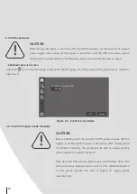
6.3.7 Emergency power off (EPO)
6.4 Parallel system start up and shut down
Do not perform the EPO operation unless there is an emergency.
CAUTION
1. After pressing the EPO button, the UPS is with no output, the
power supply for load is interrupted.
2. When the system stays in maintenance bypass status, the UPS
still has output.
CAUTION
• Before starting the parallel system, please perform the operation of 6.3 UPS Start and hut
down for each UPS.
• Before power on and testing the parallel system, please ensure that the wire connection
of input and output cables and phase sequence is right and the parallel wire is well
connected and remains in disconnection status.
• Before completely starting the parallel system, please do not start load, and ensure that
all switches of load are off.
• Before performing the parallel wire operation, please do not connect the parallel wire.
CAUTION
Step 1 Close the mains input breaker (POWER), bypass breaker (BYPASS), battery breaker of battery cabinet,
output breaker (OUTPUT) successively.
Step 2 After the power supply of UPS becomes normal and the energy flow on touch screen shows bypass
output, place the manual maintenance breaker at the back of the cabinet to OFF, at this time, the
bypass will supply power for load.
Step 3 Start inverter system.
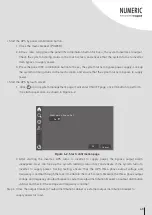
After the rectifier starts up, click the ON/OFF icon on touch screen, it will enter ON/OFF page. Select ON
icon and press the OK icon for more than 3 sec., The load is switched to mains inverter mode.
6.4.1 Start parallel system
6.3.8 Emergency power off recovery
Step 1 Ensure that the dry contact of monitor card, which is connected to the external EPO switch, is not in
emergency power off status.
Step 2 Disconnect the system input, output and battery breaker, until all system indicators are off, system
power is down completely.
Step 3 Close the mains input breaker (POWER), bypass breaker (BYPASS), battery breaker, system will boot
again and EPO goes off.
Press the EPO button on the panel or external EPO button of the system, the UPS will turn to emergency stop
status. At this time, the touch screen shows EPO protection, system red AC/DC and DC/AC indicators on and the
buzzer long beeps.
Step 1 Measure the front-end voltage and frequency of all UPS input (including mains input and bypass input)
breaker or external input distribution breaker. Voltage range: 80 V-280 V, frequency range: 40 Hz~60 Hz
(
50 Hz system
)
or 50 Hz~70 Hz
(
60 Hz system
)
.
Step 2 Connect the parallel wires, close the mains breaker and bypass breaker (keep all UPS breakers off) of
all UPS. If input power normal, rectifier will start automatically, the touch screen starts. Connect
battery to parallel system.
Step 3 Close battery breaker of each UPS’s battery cabinet (if there are many groups battery, it is necessary
to close each battery breaker and then close the total breaker between battery groups and UPS).
Measure the voltage of battery breaker (if there are many groups battery, measure the voltage of
each group battery, and then measure the voltage of total battery breaker). Ensure that the battery
connection is proper (in 2 min., all the “battery circuit abnormal” alarm on main page of the touch
screen will disappear).
Note:
The inverter also can be started by ON button on the panel, but not recommended.


