18
EN
PREMIUS
1-10 kVA
3.5.1.4. Connect the utility separately to the terminal blocks of the UPS’ Utility and Bypass inputs. Switch on the
power breaker of the distribution panel and the breakers of the UPS’ Utility and Bypass inputs. Green LEDs
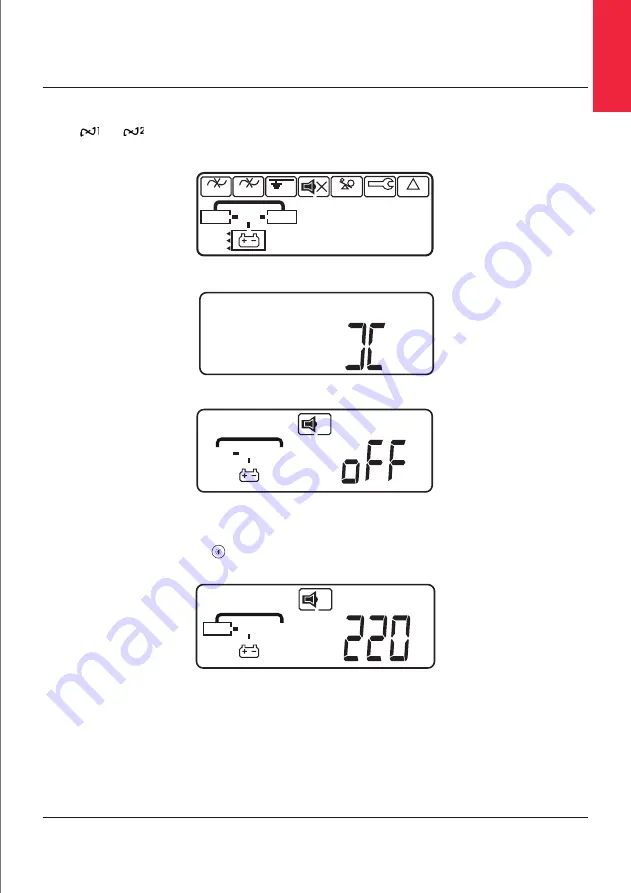
and show that the Utility and Bypass inputs are normal. UPS with parallel function enabled will
display first figure A1, then figure A2, and then figure B. Otherwise the LCD will display figure A1 directly
followed by figure B.
A1.
A2.
B.
3.5.1.5.
The UPS is in Bypass Mode now. It will proceed to self-test automatically. If no abnormal message appears
then the pre-startup of the UPS was successful and the charger starts to charge the batteries.
3.5.1.6.
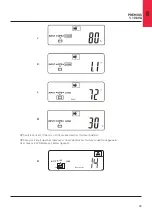
Press the UPS On Switch for approximately three seconds. The Buzzer sounds twice and the LCD
display changes from figure B to figure C.
C.
3.5.1.7.
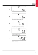
The UPS is in self-test mode again. The LCD display will change from figure C to figure D, and the UPS
will remain in battery mode for approximately four seconds. Then the display will change from figure E1 to
figure F if the self-test was successful.
INPUT
LOAD
Foult
Low
Testing
UPS
KVA
WHz
Mine
%
0
C
88.8
Parallal ID Mode
Bypass Stop
Utility Invertar
Voltage Adjust
Frequency Window
Buzzer Code
Battery Autonomy
Overload Service
Bypass
Utility
?
Wiring Fault
Alarm
!
INPUT
LOAD
UPS
INPUT
LOAD
UPS
Utility
V
Summary of Contents for PREMIUS
Page 1: ...PREMIUS 1 10 kVA User and Installation Manual ...
Page 13: ...13 2 3 2 Rear Panel 1 kVA 3 kVA FMI 3 kVA FM 2 kVA FMI 2 kVA FM 1 kVA FMI ...
Page 14: ...14 EN PREMIUS 1 10 kVA 5 kVA 6kVA FMI 5 kVA 6kVA FM 7 5 kVA 10kVA FM 7 5 kVA 10kVA FMI ...
Page 39: ...39 6 Optional Interface Cards 6 1 RSE F RS 485 card 6 2 DCE Dry Contact 6 3 SNMP Card ...
Page 50: ......


