108
In This Chapter
Power Transfer ................................................................................................. 108
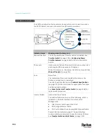
Transfer Switch Indicator Lamps ...................................................................... 114
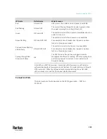
Alarm Indicator Lamps ...................................................................................... 118
Control Push Buttons ........................................................................................ 119
Testing Indicator Lamps .................................................................................... 120
Short Circuit Detection ..................................................................................... 120
Outlets .............................................................................................................. 120
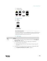
Connection Ports .............................................................................................. 121
Front LCD Display .............................................................................................. 125
Reset Buttons ................................................................................................... 163
Fuses for the Inlet Transfer Switch ................................................................... 164
Overcurrent Protectors for Outlets .................................................................. 167
Beeper .............................................................................................................. 168
Power Cycling the PX3TS .................................................................................. 168
Power Transfer
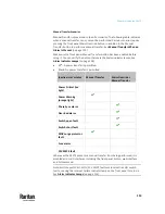
The PX3TS has two inlets: INLET 1 and INLET 2. These inlets are to connect to
diverse power sources. One inlet is configured as the primary (preferred), and
the other is configured as the standby (alternate). The factory default preferred
power source is Inlet 1, and the default alternate source is Inlet 2.
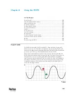
When power is available from both sources and power quality is identical, the
PX3TS selects the preferred inlet to power the load. If a power failure occurs on
the preferred source or its power quality deteriorates below an acceptable
level, the power can be transferred from one inlet to the other automatically or
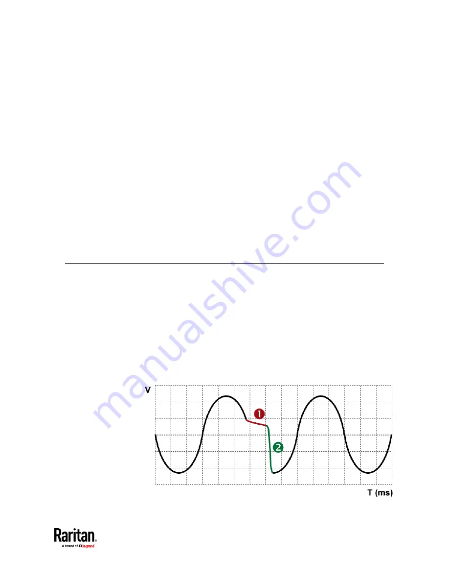
manually on the PX3TS. Power transfer does not interrupt the operation of the
connected equipment. The transfer time takes only 4-8 milliseconds (1/4 AC
cycle). See the diagram below.
Chapter 6
Using the PX3TS
Summary of Contents for Raritan PX3TS
Page 4: ......
Page 6: ......
Page 20: ......
Page 80: ...Chapter 4 Connecting External Equipment Optional 60...
Page 109: ...Chapter 5 PDU Linking 89...
Page 117: ...Chapter 5 PDU Linking 97...
Page 441: ...Chapter 7 Using the Web Interface 421...
Page 464: ...Chapter 7 Using the Web Interface 444...
Page 465: ...Chapter 7 Using the Web Interface 445 Continued...
Page 746: ...Appendix A Specifications 726...
Page 823: ...Appendix I RADIUS Configuration Illustration 803 Note If your PX3TS uses PAP then select PAP...
Page 828: ...Appendix I RADIUS Configuration Illustration 808 14 The new attribute is added Click OK...
Page 829: ...Appendix I RADIUS Configuration Illustration 809 15 Click Next to continue...
Page 860: ...Appendix J Additional PX3TS Information 840...
Page 890: ...Appendix K Integration 870 3 Click OK...
Page 900: ......


