Chapter 6: Using the PX3TS
117
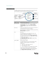
Inlet Configuration Indicator Lamps
A green LED indicates which inlet is preferred. The default is Inlet 1.
A "Preferred" inlet is the power source that you prefer using for powering the
PX3TS as long as this inlet's power is available and power quality is good. The
other inlet is the "Alternate" inlet.
The preferred inlet may be changed with the Manual Transfer button. See
Manual Transfer
(on page 112).
Active Inlet Indicator Lamps
A green LED indicates which one is the active inlet.
An "Active" inlet is the one which is powering the outlets. The other inlet is the
"Inactive" inlet. By default the "Preferred" inlet is active unless its power
quality goes critical, leading to an automatic power transfer.
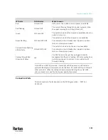
There are four operational states: normal, standby, non-redundant and off. See
Transfer Switch and Inlet Status
(on page 200).
•
In the "normal," "standby" or "non-redundant" operational state, a green
LED is present to indicate the active inlet.
•
In the "off" operational state, neither LED is green.
Summary of Contents for Raritan PX3TS
Page 4: ......
Page 6: ......
Page 20: ......
Page 80: ...Chapter 4 Connecting External Equipment Optional 60...
Page 109: ...Chapter 5 PDU Linking 89...
Page 117: ...Chapter 5 PDU Linking 97...
Page 441: ...Chapter 7 Using the Web Interface 421...
Page 464: ...Chapter 7 Using the Web Interface 444...
Page 465: ...Chapter 7 Using the Web Interface 445 Continued...
Page 746: ...Appendix A Specifications 726...
Page 823: ...Appendix I RADIUS Configuration Illustration 803 Note If your PX3TS uses PAP then select PAP...
Page 828: ...Appendix I RADIUS Configuration Illustration 808 14 The new attribute is added Click OK...
Page 829: ...Appendix I RADIUS Configuration Illustration 809 15 Click Next to continue...
Page 860: ...Appendix J Additional PX3TS Information 840...
Page 890: ...Appendix K Integration 870 3 Click OK...
Page 900: ......


