Chapter 4: Connecting External Equipment (Optional)
46
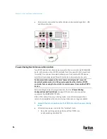
Exception: You CANNOT cascade DX-PD2C5 sensor packages. One PX3TS
supports only one DX-PD2C5.
3.
Connect the first DX sensor package to the PX3TS by plugging its cable's
connector into the RJ-45 SENSOR port of the PX3TS.
4.
If needed, connect a DPX2 sensor package to the end of the DX chain. See
Connecting a DPX2 Sensor Package to DX2, DX or DPX3
(on page 50).
Warning: DX-PD2C5 or DX2-DH2C2, and asset management strip(s) are
mutually exclusive so do NOT connect both of them to the PDU
simultaneously.
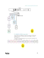
DPX3 Sensor Packages
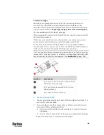
A DPX3 sensor package features the following:
•
Its connection interface is RJ-45.
•
You can cascade a maximum of 12 DPX3 sensor packages.
Numbers
Components
RJ-45 ports, each of which is located on
either end of a DPX3 sensor package.
LED for indicating the sensor status.
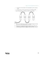
To connect DPX3 to the PX3TS:
1.
Connect a standard network patch cable (CAT5e or higher) to either RJ-45
port on the DPX3 sensor package.
2.
If you want to cascade DPX3 sensor packages, get an additional standard
network patch cable (CAT5e or higher) and then:
Summary of Contents for Raritan PX3TS
Page 4: ......
Page 6: ......
Page 20: ......
Page 80: ...Chapter 4 Connecting External Equipment Optional 60...
Page 109: ...Chapter 5 PDU Linking 89...
Page 117: ...Chapter 5 PDU Linking 97...
Page 441: ...Chapter 7 Using the Web Interface 421...
Page 464: ...Chapter 7 Using the Web Interface 444...
Page 465: ...Chapter 7 Using the Web Interface 445 Continued...
Page 746: ...Appendix A Specifications 726...
Page 823: ...Appendix I RADIUS Configuration Illustration 803 Note If your PX3TS uses PAP then select PAP...
Page 828: ...Appendix I RADIUS Configuration Illustration 808 14 The new attribute is added Click OK...
Page 829: ...Appendix I RADIUS Configuration Illustration 809 15 Click Next to continue...
Page 860: ...Appendix J Additional PX3TS Information 840...
Page 890: ...Appendix K Integration 870 3 Click OK...
Page 900: ......


