32
®
WARNING
The instructions in this chapter are not addressed to a normal operator but to a specialized technician, authorised
to work only if he uses the Individual Protective Gear mentioned in Chapter 3.
5.1
Safety rules and regulations
Prima di eseguire qualsiasi operazione di installazione, leggere e applicare quanto di seguito riportato:
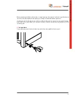
1. Warning: device with high leakage current, it is essential to ensure ground protection before connecting power. It is
necessary to check that the distribution panel, which connects the UPS, has a secure connection to the circuit ground
and adequate protection, as required by law.
2. The installation of the UPS Trimod® units must be provided with a fixed type circuit breaker. There shall be no
connection to the mains through a plug of the traditional type.
3. The framework of power supply or disconnection device, must be installed near the equipment and be easily
accessible.
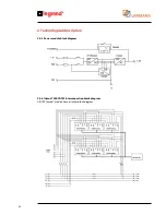
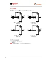
4. A circuit protection against return voltage must be provided externally to the UPS (backfeed protection). See diagrams
on the next page.
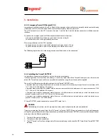
5. You will have to affix a “warning” label on all power disconnects the power supply placed away from the UPS in order
to alert the service personnel that the circuit is connected to a UPS. The label must contain the following text (or
equivalent):
Before working on this circuit
- Isolate Uninterruptible Power System (UPS)
- Then check for Hazardous Voltage between all terminals
including the protective earth
Risk of Voltage Backfeed
The UPS Trimod® is equipped with an auxiliary contact for enabling the external circuit backfeed protection. The auxiliary
contact is made with a relay C / NC / NO and is available on the terminal pole “BACKFEED PROTECTION” in the terminal
box of the UPS.
If the UPS detects a condition of return voltage, the relay is energized and changes state, enabling the cutting of input
lines that must be realized externally as indicated in the schematic below.
The characteristics of relay contacts are:
• Maximum switching voltage: 250Vac.
• Applicable current: 5A, PF = 1.
5. Installation
Summary of Contents for Trimod 10 kVA
Page 1: ...Trimod Operating and Maintenance Manual Part LE05768AA 07 12 01 GF ...
Page 2: ... 2 EN ENGLISH 3 Trimod ...
Page 12: ...12 UPS Trimod 10 UPS Trimod 10 15 20 2 3 Models 2 Technological description ...
Page 13: ...Trimod Operating and Maintenance Manual 13 UPS Trimod 10 15 20 UPS Trimod 30 TT ...
Page 14: ...14 UPS Trimod 30 TM UPS Trimod 40 2 Technological description ...
Page 15: ...Trimod Operating and Maintenance Manual 15 UPS Trimod 60 ...
Page 16: ...16 2 Technological description UPS Trimod BATTERY UPS Trimod BATTERY 2 ...
Page 42: ...42 5 Installation UPS Trimod 30TM ...
Page 43: ...Trimod Operating and Maintenance Manual 43 UPS Trimod 30TT ...
Page 44: ...44 UPS Trimod 40 60 5 Installation ...
Page 46: ...46 5 Installation ...


