Trimod MCS
U
ser manual
15
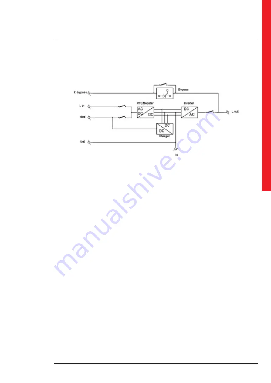
The power modules are housed on shelves also called “tunnels” that can house three modules.
The block diagram of the power module is the following:
Batteries
The battery modules are designed for easy insertion into the dedicated cabinet and they do not need any operation for
their connection. A drawer consists of five 12V-9Ah batteries, connected in series and thanks to the Plug & Play connec-
tion it is easy to extract and insert it in the cabinet.
The nominal battery voltage for the Trimod MCS is 240Vdc, therefore a complete branch consists of four battery drawers
(for a total of twenty 12Vdc batteries) that form what is called KB (Battery Kit).
In order to ensure the maximum level of safety, the voltage of each drawer is properly isolated into two branches of 24 V
and 36 V and it is only restored when the drawer is completely inserted into its housing.
This allows conformity with the standard EN 62040-1 on electrical safety that requires the use of adequate protection and
particular care when handling dangerous voltages above 50 Vdc where direct contact is possible.
The battery operation autonomy of the EPS can be increased by adding more battery drawers in multiples of four, using
both the seats in the EPS cabinet if available, and the seats in the additional modular battery cabinets.
Digital display and alarm display
Trimod MCS is managed by a microprocessor-type command board (according to the version) and it has a backlit LCD
alphanumeric display with twenty characters on four lines.
The display is incorporated in the control panel where there is also a high-brightness operating status indicator with
traffic light type green-yellow-red.
Five keys situated near the display enable the user to display the operating data, set the operating parameters, analyse
the status of the individual power modules, select the language in which the messages are to be displayed and carry out
a guided set of functional tests and procedures.
BCM - Battery Charger Module 3 108 51
The additional battery charger module works in parallel and in sync with the battery chargers in the power modules and
it is managed by the same algorithm that governs the recharging cycle. Every additional battery charger module provides
up to 15A of charge current that are added to the current of the battery chargers inside the power modules. Every power
module can provide up to 2.5A of charge current. This guarantees a reduction of the charge time in installations requiring
long autonomies and increases the availability of the UPS after a black out. During operation, the module takes current
from the input phase where it is installed.
It is possible to install any quantity of BCMs as long as there is at least one power module and enough empty slots inside
the EPS cabinet. All the information regarding the operating status of the BCM is given by the LED on the front of the
module and by what is shown on the EPS display.
The module is managed by a microprocessor to optimize performance and reliability. It is recommended to install it to-
gether with a battery cabinet with capacity exceeding 60 Ah.
ECO MODE
One functioning mode of Trimod MCS is called “eco mode”. With this mode it is possible to save energy while guaran-
teeing uninterruptability of the power supply to the load connected. During the functioning in eco mode, the load
is powered directly from the electrical mains through the automatic bypass circuit inside the power modules. This
means that the output voltage and frequency are the same as the mains. The advantage obtained in the eco mode is
a greater electrical efficiency and consequently a reduction in consumption. If the output voltage leaves the window
of tolerance (-20% / +15% of the voltage set on the output), the EPS actuates its inverter stage and powers the load
with the energy stored in the batteries. The autonomy during the battery operation depends on the configuration of
the UPS (nominal power, battery capacity) and on the percentage of load applied. When the mains are back within the
tolerance values, the EPS switches automatically back to the eco mode. It is possible to change the operating mode
between on-line and eco mode (and viceversa) both with the EPS on and with the UPS off (in this case entering the
Service Mode).
Summary of Contents for Trimod MCS 10
Page 1: ...Item LE10960AA 01 19 01 CT Trimod MCS User manual ...
Page 2: ...2 UK ENGLISH 3 Trimod MCS ...
Page 16: ...16 3 3 Models Trimod MCS 3 5 10 Trimod MCS 7 15 3 Technological description ...
Page 17: ...Trimod MCS User manual 17 Trimod MCS 30 Trimod MCS 20 ...
Page 18: ...18 Trimod MCS 40 Trimod MCS 60 Trimod MCS 80 3 Technological description ...
Page 58: ...58 ...
Page 59: ...Trimod MCS User manual 59 ...


