background image

LOW VOLTAGE INPUTS

Four +12-24VDC input wires are provided to control the load relay. The inputs may 
be used in combination or individually, depending on the needs of the application. 
See the WIRING section for wiring information.

Maintained Inputs:

Control ON

 (Blue) – This input is intended for occupancy sensor input. 

Applying 12-24VDC closes the relay.  
Remove the voltage and the relay opens if no other input is holding it closed.

Hold ON

 (Orange) – This input is intended for timer or panel input. 

Applying 12-24VDC closes the relay.   
Remove the voltage and the relay opens if no other input is holding it closed.
It overrides Control ON input. 

Hold OFF

 (Brown) – This input is used for timer, panel, BAS or load shed input.

Applying 12-24VDC opens the relay. 
Remove the voltage and the relay can accept any other input. 
It overrides Control ON and Hold ON inputs.  

Momentary Input:

Manual ON/OFF

 (Grey) – This 

input is for a low voltage 
momentary switch. Applying 
12-24VDC momentary input 
changes the relay to the 
opposite state. 
It overrides Control ON, Hold 
ON and Hold OFF inputs. 

BI-LEVEL CONTROL 
WITH MANUAL ON

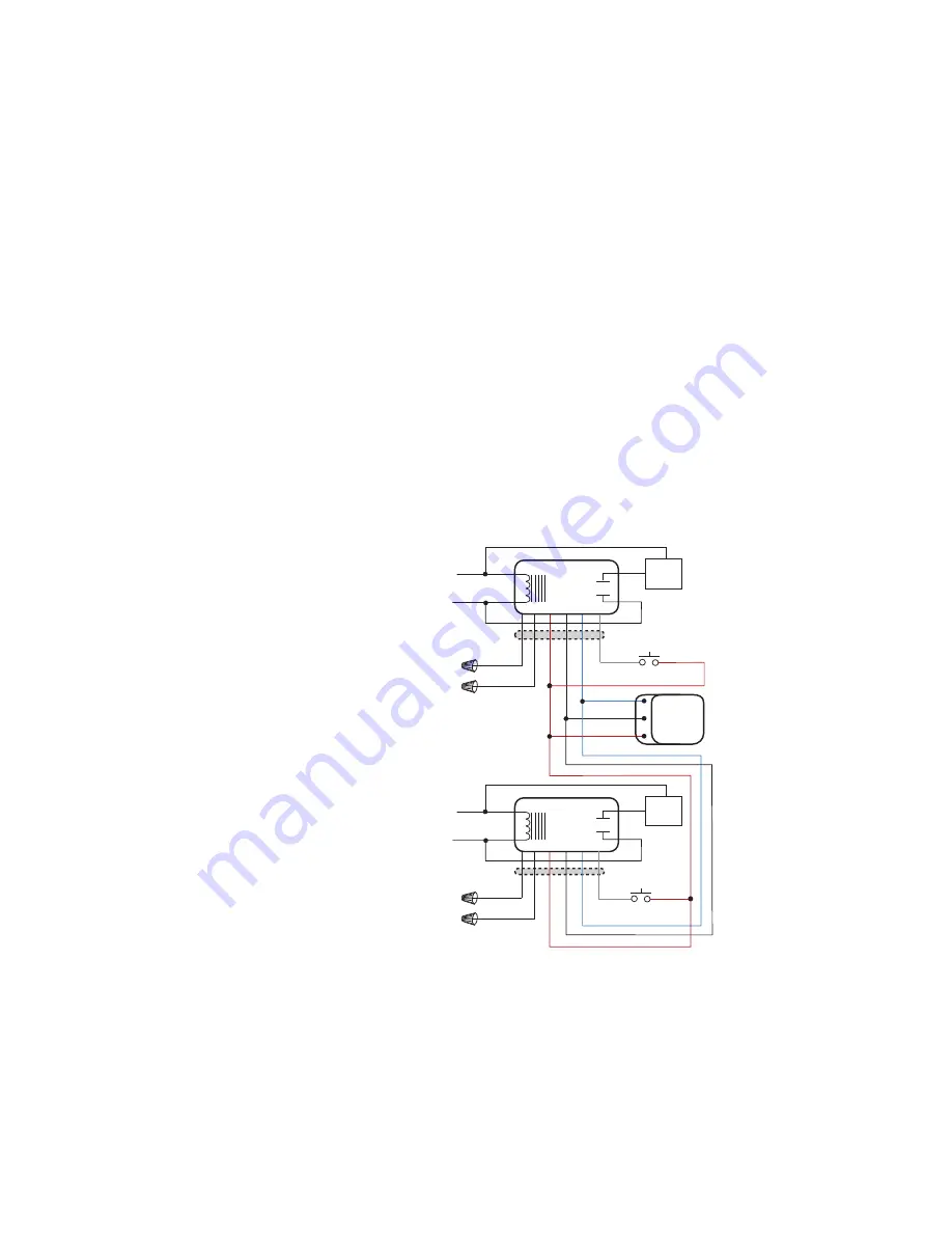
The diagram to the right shows 
how to confi gure BZ-150s to 
provide bi-level lighting control 
with both Automatic ON and 
Manual ON features.

As shown, upon occupancy 
detection load A turns ON 
automatically. To turn ON load B 
the user must press momentary 
switch B. Both loads turn OFF 
automatically when the sensor 
time delay expires, or manually 
using switch A and B.

+24VDC

Common

Red

White

Neut.

BZ-150

(A)

AUTO ON

Blue

Black

Red

Lighting

Load (A)

277VAC

Black

120VAC

Any 3-Wire

24VDC

Sensor 

Hot

Red

Brown

Orange

Control

Low Voltage Wires

Red

White

Neut.

BZ-150

(B)

MANUAL ON

Blue

Black

Red

Lighting

Load (B)

277VAC

Black

120VAC

Hot

Red

Brown

Orange

Gr

ey

Momentary Switch (B)

Low Voltage Wires

Gr

ey

Momentary Switch (A)

Parallel interconnect for bi-level load control 

from a single sensor with manual ON

Summary of Contents for WattStopper BZ-150

Page 1: ...quirements Ballast 20amp 120 277VAC Incandescent 20amp 120VAC Motor 1HP 120 240VAC Output 225mA 24VDC with relay connected Low Voltage Input Control ON 12 24VDC Hold ON 12 24VDC Hold OFF 12 24VDC Manual ON momentary switch required 12 24VDC Operating Temperature 32 104 F 0 40 C Santa Clara CA 95050 ...

Page 2: ... After initial wiring is complete check wiring diagrams to verify the power pack is wired correctly Improper wiring can cause damage to the power pack lighting system occupancy sensor and other control devices INSTALLATION WARNING TURN POWER OFF AT CIRCUIT BREAKER BEFORE INSTALLING POWER PACKS WIRING Low Voltage High Voltage 24VDC Common Red White Neut Power Pack Blue Black Red Dry Contact Lightin...

Page 3: ...xpires e g as might be required for a presentation Pressing the momentary switch before the sensor time delay expires turns ON the load When the occupancy sensor s time delay expires the BZ 150 reverts to Auto ON mode and it turns ON the load with the next input from the occupancy sensor Manual ON Mode Switch RIGHT Occupants must press the low voltage momentary switch to turn ON the load When the ...

Page 4: ... inputs Momentary Input Manual ON OFF Grey This input is for a low voltage momentary switch Applying 12 24VDC momentary input changes the relay to the opposite state It overrides Control ON Hold ON and Hold OFF inputs BI LEVEL CONTROL WITH MANUAL ON The diagram to the right shows how to configure BZ 150s to provide bi level lighting control with both Automatic ON and Manual ON features As shown upo...

Page 5: ...them OFF for a presentation The BZ 150 is set for the Auto ON Mode and the occupancy sensor time delay expired The BZ 150 reverted to Auto ON and then motion was detected Consider increasing occupancy sensor sensitivity and or time delay Generate more motion during presentations The load does not turn ON with occupancy detection Mode Switch is set to Manual ON Hold OFF input is active The load doe...

Page 6: ...her indirect damages with respect to loss of property revenue or profit or cost of removal installation or reinstallation 2800 De La Cruz Boulevard Santa Clara CA 95050 Technical Support 800 879 8585 www wattstopper com 08616r3 6 2009 ORDERING INFORMATION Load Range Catalog No Description Input Voltage Ballast A Incan A Motor hp Output BZ 50 Power Pack 120 230 277VAC 50 60Hz 20 20 1 24VDC 225mA w r...

Reviews: