background image

Wattstopper


®

DLM Wireless Slim Switches with IPv6/Bluetooth(R) Low Energy Technology

Installation Instructions • Instructions d’Installation • Instrucciones de Instalación

No: 31762 – 12/21  rev. 1

Catalog Numbers • Les Numéros de Catalogue • Los Números de Catálogo: 

LMSW-610-S, LMSW-611-S, LMSW-622-S, LMSW-641-S

Country of Origin: Made in China • Pays d’origine: Fabriqué en Chine • País de origen: Hecho en China

SPECIFICATIONS

Power Supply .......................... Battery powered, CR2032 Battery, 3VDC
Connection to DLM Network .... Wireless via LMRC-611 room controllers 

   .............................................................................. or LMBC-650 
Wireless Radio .................................Single, Concurrent 802.15.4 and  

   ............................................ Bluetooth Low Energy, 2.4GHz
Wireless Communication
 

IPv6 Mesh (6LoWPAN) Range ....................................up to 60 ft.


Bluetooth low energy Range .......................................up to 60 ft.


60 ft. max. between LMSW-6xx-S and room controller or bridge

Wireless Encryption .................................. AES-128 bit symmetric key
Environment ........................................................ For Indoor Use Only
 

Operating Temperature ........................32° to 140°F (0° to 60°C)


Storage Temperature ......................... 23° to 140°F (-5° to 60°C)


Relative Humidity ..............................5 to 95% (non condensing)

Compliance/Regulatory
 

UL, cUL, FCC, IC

 RoHS
 

Bluetooth certified

NOTE: 

Installation shall be in accordance with all applicable 

regulations, local, and NEC codes

Once paired to a wireless room controller or wireless bridge, 

adjustment via the DLM Configuration App or LMCS-100 may 

be required to meet the local energy code where installed.

The DLM Wireless Slim Switches are wireless battery powered wall 

switches intended for operation with wireless room controllers or 

wireless bridges in hybrid rooms. 

Do not apply cleaning solvent directly onto unit. Apply cleaning solvent onto 

a cloth, then wipe the unit to clean it.

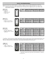
BUTTONS AND INDICATORS

Status/Battery

Life LED

Tap when load OFF: Turn ON to last level

Tap when load ON: Go to full bright

Press & Hold: Ramp Up

Tap: Fade to OFF

Press & Hold: Ramp Down

Button(s) can be set  

to toggle on/off or 

to function as a 

scene switch

Configuration Button

(Right side of Legrand badge)

LED Color

Function

Red/Green/Blue 

Flash

Unit Boot Up

Green, 1 Blink

Config Button Pressed

Blinking Green

Push to Pair Mode

Red, 1 Blink

In normal operation, if any button 

press, indicates low battery
Also blinks if Reset button on back is 

pressed

Blinking Red

Push n’ Learn Mode

White

Button or Rocker pressed during 

normal operation

LMSW-610-S

LMSW-611-S

LMSW-622-S

LMSW-641-S

Summary of Contents for Wattstopper LMSW-610-S

Page 1: ...ified NOTE Installation shall be in accordance with all applicable regulations local and NEC codes Once paired to a wireless room controller or wireless bridge adjustment via the DLM Configuration App or LMCS 100 may be required to meet the local energy code where installed The DLM Wireless Slim Switches are wireless battery powered wall switches intended for operation with wireless room controlle...

Page 2: ...le in a three gang application remove the right alignment wing from the left switch both wings from the middle switch and the left wing from the right switch as shown below 4 Peel the adhesive protector off of the rear of the switch 5 Install with each switch in contact with the adjacent switch es After the first switch has been installed by pressing and holding for 5 seconds place the next switch...

Page 3: ...ming Ballast LED Driver etc Load Examples any relay A Switched etc B Class 1 Dimming Class 2 also available LMSW 622 S Wireless Slim Switch HYBRID ROOM CONNECTION WITH WIRED LIGHTING CONTROL AND DLM SHADING Distance Recommendations 60 max between LMSW 6xx S and mobile device 60 max between LMSW 6xx S and room controller or bridge 10 minimum and 100 maximum between LMBR 650 and room controller or b...

Page 4: ...For each device the load will toggle during step 3 and its config LED will turn solid green 4 Exit PtP mode From any device press the Config button 3 times After a few seconds the LED on each Room controller switch or sensor currently in PtP mode will flash either white or a red green blue sequence and reboot leaving the default network and migrating to the new network Then the LED on the room con...

Page 5: ...n three minutes the LMBC 650 will exit PtP mode 1 Enter PtP mode on the LMBC 650 Using a pointed tool press the Config button three times within three seconds until the LED on the LMBC 650 flashes green 2 Enter PtP mode on the LMSW 6xx S Press the Config button right side of Legrand badge three times As with the wireless bridge the LED on the switch will flash green 3 Pair the LMSW 6xx S Press the...

Page 6: ...t Press Default Hold Button 1 All Lighting Loads Toggle On Off Toggle Ramp Rocker 1 Up All Lighting Loads Send to 100 Raise Rocker1 Down All Lighting Loads Send to Off Lower Button 2 All Lighting Loads Toggle On Off Toggle Ramp Rocker 2 Up All Lighting Loads Send to 100 Raise Rocker 2 Down All Lighting Loads Send to Off Lower Toggle Ramp Button press actions will toggle loads between minimum and m...

Page 7: ...ddle on the wireless switch The LED will switch to the other color and stay lit for one second and then resume blinking red Each time you press and hold the paddle or button it will cycle to the next option Blue The button or paddle is bound to the load Red The button or paddle is not bound to the load Step 3 Exit Push n Learn Press and hold the Config button until the red LED turns OFF approximat...

Page 8: ...s been tested and found to comply with the limits for a Class B digital device pursuant to part 15 of the FCC Rules These limits are designed to provide reasonable protection against harmful interference in a residential installation This equipment generates uses and can radiate radio frequency energy and if not installed and used in accordance with the instructions may cause harmful interference ...

Reviews: