39
2009+ REMOVAL
1. Disconnect turn signal from wire harness.
2. Using an electrical pin removal tool, remove
pins from connector block.
3. Remove clamp and washer from taillight; re-
move turn signal.
2009+ REPLACEMENT
1.
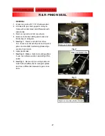
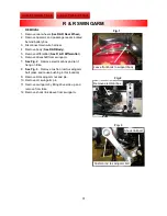
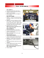
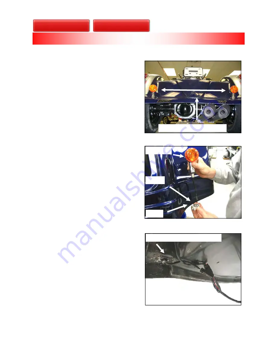
See Fig. 1
. Install new turn signals ensuring
that screws in signals are facing inward, toward
each other.
2.
See Fig. 2
. Secure turn signal with (1) clamp
and (1) washer. Tighten clamp bolts and set
screws on each side of signal. Tighten outside
screw first (which will pull it to outside of body),
then tighten inside screw to level turn signal.
3. Repeat procedure for other side.
NOTE: Wire harness lead with brown wire
goes on right side of body.
2005-2008 REMOVAL
1. Disconnect turn signal from wire harness.
2. Using an electrical pin removal tool, remove
pins from connector block.
3. Remove self-threading nut from turn signal;
remove turn signal.
2005-2008 REPLACEMENT
1. Install turn signals ensuring that screws in turn
signals are facing inward, toward each other.
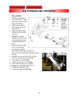
2.
See Fig. 3
. Install left side turn signal with (1)
self-threading nut. Tighten nut using 14mm
wrench
3. Repeat previous steps for right side turn signal
installation.
4. Connect taillights and turn signals to wire har-
ness and route through body clips.
NOTE: Wire harness lead with purple wire
goes on right side of body.
5. Test turn signals.
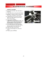
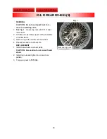
Fig. 2
Fig. 1
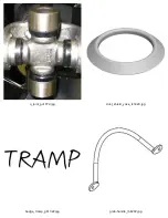
Clamp
Washer
Turn Signal
Turn signals screws face inward
Fig. 3
Secure signal with self-threading nut
R & R TURN SIGNAL

