background image


4


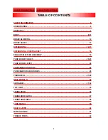
SAFETY INFORMATION.................................................................................................................... 5 
 
AXLE BEARING ................................................................................................................................. 6 
 
AXLE SEAL ........................................................................................................................................ 7 
 
BODY ............................................................................................................................................. 8-11 
 
BRAKE BLEEDING .......................................................................................................................... 12 
 
BRAKE SHOES ................................................................................................................................ 13 
 
DIFFERENTIAL ........................................................................................................................... 14-17 
 
DIFFERENTIAL COVER GASKET .................................................................................................. 18 
 
EXHAUST, MUFFLER ASSEMBLY................................................................................................. 19 
 
PARK BRAKE CABLES ............................................................................................................. 20-23 
 
PARK BRAKE LEVER ..................................................................................................................... 24 
 
PASSENGER FOOTPADS............................................................................................................... 25 
 
PASSENGER GRAB HANDLES...................................................................................................... 26 
 
PINION SEAL .............................................................................................................................. 27-29 
 
REAR WHEEL(S) ............................................................................................................................. 30 
 
SWINGARM ................................................................................................................................. 31-34 
 
TAIL LIGHT....................................................................................................................................... 35 
 
TRUNK DOOR .................................................................................................................................. 36 
 
TRUNK DOOR LATCH..................................................................................................................... 37 
 
TRUNK DOOR SEAL ....................................................................................................................... 38 
 
TURN SIGNAL.................................................................................................................................. 39 
 
REAR U-JOINT................................................................................................................................. 40 
 
WIRE HARNESS .............................................................................................................................. 41 
 
TORQUE SPECS.............................................................................................................................. 42 


TABLE OF CONTENTS 

Jump to Flat Rate Times 

Jump to Parts and Pricing 

Summary of Contents for TRAMP 2009

Page 1: ...PUB0020 Powered by Suzuki 2009 SERVICE INFORMATION 2009 SERVICE INFORMATION SERVICE PROCEDURES SERVICE PROCEDURES FLAT RATE TIMES FLAT RATE TIMES PARTS PRICE LIST PARTS PRICE LIST ...

Page 2: ...___ __________________________________________________________ How can this manual be improved __________________________________________________________ __________________________________________________________ __________________________________________________________ __________________________________________________________ Name ______________________________________________________ Occupatio...

Page 3: ...familiar with the service procedures before starting any work Some proce dures require the use of special tools Use only the proper tools as specified If you have any doubt as to your ability to perform any of the procedures outlined in this service supplement or within the posted flat rate times contact Lehman Trikes before you start work at 1 888 394 3357 2009 All rights reserved Lehman Trikes p...

Page 4: ...LER ASSEMBLY 19 PARK BRAKE CABLES 20 23 PARK BRAKE LEVER 24 PASSENGER FOOTPADS 25 PASSENGER GRAB HANDLES 26 PINION SEAL 27 29 REAR WHEEL S 30 SWINGARM 31 34 TAIL LIGHT 35 TRUNK DOOR 36 TRUNK DOOR LATCH 37 TRUNK DOOR SEAL 38 TURN SIGNAL 39 REAR U JOINT 40 WIRE HARNESS 41 TORQUE SPECS 42 TABLE OF CONTENTS Jump to Flat Rate Times Jump to Parts and Pricing ...

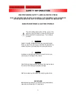
Page 5: ... indicates a potential hazard that may result in severe injury or death to the operator by stander or person s inspecting or servicing the vehicle WARNING Indicates a potential hazard that may result in minor per sonal injury or damage to the vehicle CAUTION CAUTION indicates special precautions that must be taken to avoid vehicle damage or property damage CAUTION NOTE provides key information by ...

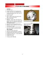
Page 6: ...e of flange for removal 7 Remove axle and backing plate from tube 8 See Fig 2 Remove and discard locking collar using a grinder or chisel 9 Place a bearing splitter tool under bearing place axle in a press and press bearing off REPLACEMENT 1 Install new bearing using a press 2 Install new collar provided with new bearing 3 Reinstall backing plate and axle into axle tube 4 Reinstall axle flange nut...

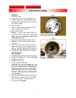
Page 7: ...seal carefully when in stalling Seal can easily become damaged 10 Set seal into position and secure with proper seal installation tool REPLACEMENT 1 Reinstall backing plate and axle into axle tube 2 Reinstall axle flange nuts Torque to 44 ft lbs 3 Reinstall brake drums 4 Reinstall rear wheels 5 Torque lug nuts to 75 ft lbs CAUTION Do not over fill differential Pos sible axle seal failure and conta...

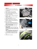
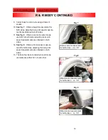
Page 8: ... located inside trunk 10 Remove grab handles 11 Remove grab handle brackets Remove re maining body mount bolts from top chrome rail NOTE Get help to support body while re moving the last two bolts 12 Carefully remove body and set safely aside REPLACEMENT CAUTION Use caution when adding equip ment to new body Paint can become easily damaged NOTE If installing new body begin at step 1 If reinstallin...

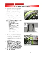
Page 9: ... outside body 6 See Fig 4 While one person steadies body from behind insert 2 5 16 x 3 NC button head bolts front 2 rubber washers 2 5 16 x 1 1 2 plated fender washer 2 body mount bushing 2 1 4 20 lock nut and 2 5 16 SS lock washer and leave bolts loose for body adjustment 7 The rear fender brace holes will include the following 2 5 16 x 3 NC button head bolts 2 rubber washer 2 5 16 x 1 1 2 plated...

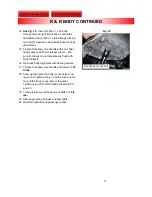
Page 10: ...dy until equal measurements are obtained on both sides 12 See Fig 9 Obtain a front to back measure ment for both sides adjusting the body until equal measurements are obtained on both sides 13 The body has been centered when all meas urements are within 1 8 of each other Obtain same measurement for both sides or 1 8 Obtain same measurement for both sides or 1 8 Obtain same measurement for both sid...

Page 11: ... footrests 16 Re check body alignment with framing square 17 Tighten front body mount bolts and torque to 16 ft lbs 18 Snug up top frame rail body mount bolts mak ing sure to tighten evenly on both sides so as to not pull the body to one side or the other Tighten using 3 16 Allen head socket and 1 2 wrench 19 Torque top frame rail body mount bolts to 16 ft lbs 20 Reconnect wiring harness and test ...

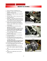
Page 12: ...t previous steps on right side bleeder screw using proper sequence 9 On left side attach 1 4 wrench and brake bleeder to bleeder screw 10 Pump brake pedal 7 8 times and hold pedal down after last pump 11 With brake pedal held down open bleeder screw with a 1 4 wrench Bubbles will surface into brake bleeder hose Note Maintain fluid level in reservoir to pre vent more air from entering brake system ...

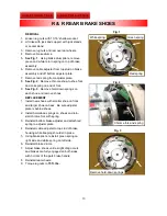
Page 13: ...aller shoe on front and larger shoe on back Be sure adjuster plate is behind shoes 2 Install hold down springs on shoes and rein stall chrome fork with spring 3 Reinstall bottom brake adjuster and attach red spring to adjuster plate 4 Reinstall cable adjuster to top stud of brake housing while keeping shoulder in place 5 Using brake pliers reinstall green spring on right side and white spring on l...

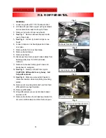
Page 14: ...s 11 Remove cable ties holding park brake and brake lines to swingarm 12 See Fig 3 Remove U bolts from U joint CAUTION Differential is very heavy Get help with removal 13 See Fig 4 Mark area around bolt heads to reference location when reinstalling mounting plates 14 Remove 8 mounting bolts and nuts that hold differential to swingarm plates 15 Remove differential 16 Drop differential out over park...

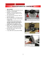
Page 15: ...ON Driveshaft interference with swingarm housing may cause equipment damage or lead to an accident Verify proper clearance and adjust as needed 5 See Fig 7 Center differential to body using a framer s square Adjust differential until equal measurements are obtained on both sides 6 Spin drive shaft to check clearance in both front and rear locations 7 Torque differential mounting bolts to 47 ft lbs...

Page 16: ...12 Remove differential fill plug and apply 9L 30 oz of 80w90 gear oil Replace fill plug 13 Torque fill plug to 40 ft lbs CAUTION Do not over fill differential Pos sible axle seal failure and contamination of rear brake linings can occur 14 See Fig 9 Attach braided brake line from master cylinder to brass brake T with banjo bolt and two sealed washers 15 Tighten banjo bolts at brass T using 3 8 wre...

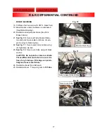
Page 17: ...22 See Fig 11 Secure park brake cables using 3 high temp zip ties 23 See Fig 12 Secure vent tube using 2 black zip ties CAUTION Do not pinch or block vent tube Check differential vent tube to be sure it is free of any blockage Blockage can poten tially lead to axle seal failure 24 Reinstall exhaust See Exhaust 25 Reinstall wheels Torque lug nuts to 75 ft lbs Fig 10 Fig 11 Fig 12 Secure brake line ...

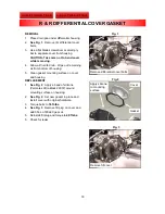
Page 18: ...housing REPLACEMENT 1 See Fig 2 Apply a bead of silicone Permatex Ultra Black 22072 around mounting surface on housing 2 See Fig 2 Set new gasket in place and install cover with original hardware 3 Torque bolts to 18 ft lbs 4 See Fig 3 Remove fill plug on cover and add 30oz of 80w90 gear oil 5 Reinstall fill plug and torque to 40 ft lbs 6 Check for leaks Fig 1 Fig 2 R R DIFFERENTIAL COVER GASKET F...

Page 19: ...PLACEMENT 1 Install LH pipe into front head pipe and loosely attach band clamps Ensure that gasket is in place 2 See Fig 2 Attach crossover pipe by pushing and turning to seat it fully into pipe 3 Pull front pipe into place while positioning rear head pipe to head 4 Install rear head pipe bolts and tighten while pulling LH pipe forward onto front head pipe 5 Tighten band clamps on exhaust park bra...

Page 20: ...g bracket Pull brake lever up and remove inner nuts 5 See Fig 2 Loosen and remove hardware from park brake bracket 6 See Fig 3 Cut and remove all cable ties at taching park brake cables to differential and swingarm 7 Remove left and right brake drums Fig 1 Remove outer nuts Fig 2 Remove hardware Fig 3 2 4 Black cable ties 3 White high temp cable ties R R PARK BRAKE CABLES Jump to Flat Rate Times J...

Page 21: ...m u shaped lever 9 See Fig 5 Compress fingers of cable insert with needle nose pliers or equivalent to allow cable insert to slide out of backing plate and remove cable from drum Fig 4 Release cable from lever Fig 5 Compress fingers on cable insert R R PARK BRAKE CABLES CONTINUED Jump to Flat Rate Times Jump to Parts and Pricing ...

Page 22: ... 7 Re install long left inside park brake cable to inside left park brake bracket slot and fasten with hardware 5 See Fig 8 Re install short right outside park brake cable to outside right park brake bracket slot and fasten with hardware 6 Re install cable clamp in same location 7 Bend cable clamp away from exhaust R R PARK BRAKE CABLE CONTINUED Fig 6 Fig 7 Left inside cable Right outside cable 2 ...

Page 23: ...l vent tube to be sure it is free of any blockage Blockage can potentially lead to axle seal failure 10 See Fig 10 Re install cable ties in same loca tion 11 Reinstall park brake boot and hardware 12 Reinstall rear wheels 13 Torque lug nuts to 75 ft lbs R R PARK BRAKE CABLE CONTINUED Fig 9 Fig 10 2 4 Black cable ties 3 White high temp cable ties Re install bracket hardware R R PARK BRAKE CABLES CO...

Page 24: ...3 1 Place new park brake lever within park brake bracket ensuring ratchet is secure on cross brace Attach with large clevis pin using snap ring pliers 2 Attach cable pulling bracket to hand brake us ing small clevis pin and cotter key using needle nose pliers 3 Adjust jam nuts on park brake cable until full engagement of park brake is achieved with three clicks of park brake lever Tighten jam nuts...

Page 25: ...ads by lifting outside edge and rear of footpad and turn toward inside of trike Lift remainder of footpad and stud out of body pocket REPLACEMENT NOTE Do not over tighten hardware 1 Install new footpads and secure with original hardware 2 Reinstall side covers Fig 3 Fig 2 Fig 1 Remove right side cover Remove left side cover R R PASSENGER FOOTPADS Remove hardware Jump to Flat Rate Times Jump to Par...

Page 26: ...ng hardware from frame rails and grab handles 2 Carefully remove grab handles REPLACEMENT 1 Install new grab handles with same hardware Fig 1 Remove grab handles R R PASSENGER GRAB HANDLES Jump to Flat Rate Times Jump to Parts and Pricing ...

Page 27: ...ave rear driveshaft yoke and U joint in place on driveshaft maintaining phase align ment to front U joint 6 Apply park brake 7 See Fig 2 Make a mark on mounting plates to use as a reference when reinstalling differ ential 8 See Fig 3 Remove 8 mounting bolts and nuts that hold differential to swingarm plates and move differential rearward to gain clear ance R R PINION SEAL Fig 1 Remove U bolts Fig ...

Page 28: ...ar and clean housing surface 14 See Fig 4 Apply silicone to edge of new seal where it will mate into housing 15 Carefully tap seal into housing Apply a thin coat of oil to seal surface 16 Apply a small amount of silicone to splines on backside of yoke and install until it bottoms against front pinion bearing 17 Install pinion nut torque to 120 ft lbs Make sure yoke spins and has no endplay or side...

Page 29: ...op to bottom 24 Torque u bolts to 20 ft lbs CAUTION Do not over tighten u bolts The bearing cups may distort causing prema ture joint failure or u bolts may break 25 Check differential fluid and add appropriate amount of 80w90 fluid if necessary Differen tial fluid capacity for the Tramp is 30 oz 26 Install new wheels on wheel studs 27 Install lug nuts and tighten in a criss cross pattern 28 Torqu...

Page 30: ...nds or center stand 3 Remove lug nuts and remove rear wheel 4 Repeat procedure on other side REPLACEMENT 1 Install new wheels on wheel studs CAUTION Use caution to not cross thread studs 2 Install lug nuts and tighten in a criss cross pattern 3 Torque lug nuts to 75 ft lbs R R REAR WHEELS Fig 1 Remove lug nuts R R REAR WHEEL S Jump to Flat Rate Times Jump to Parts and Pricing ...

Page 31: ...ectrical box and let it hang on trike 8 See Fig 3 Remove cushion rod to swingarm bolt save and reuse bushing in this location 9 Remove RH swingarm nut and pin 10 Remove LH swingarm pin 11 Remove swingarm by tilting drive side up and remove from trike 12 Remove shock link sleeve from swingarm Fig 1 Leave front bolts to support body Fig 2 Remove electrical box R R SWINGARM Fig 3 Shock link bolt Cush...

Page 32: ...gain creating zero lash no resistance between swingarm pin and bearing 6 Install RH pivot pin lock nut to left side swin garm pin using Loctite 242 on threads 7 Torque RH jam nut to 72 ft lbs 8 Torque LH swingarm pin to 72 ft lbs 9 Check for free movement of swingarm 10 See Fig 5 Install OEM bolt and nut to swingarm through shock links 11 Torque shock link bolt to 56 ft lbs Fig 5 Fig 4 3 4 Item Pa...

Page 33: ... Driveshaft interference with swingarm housing may cause equipment damage or lead to an accident Verify proper clearance and adjust as needed 15 Make sure differential is in the highest possible position relative to swingarm 16 Center differential to motorcycle frame 17 Torque differential mounting bolts to 47 ft lbs Fig 7 Fig 6 Support differential with jack stands R R SWINGARM CONTINUED Pinion s...

Page 34: ...with DOT 4 brake fluid 24 Secure left side braided brake line and park brake cable to left side of swingarm using 3 black zip ties 25 See Fig 9 Secure vent tube and park brake cables using 3 high temp zip ties 26 See Fig 10 Secure vent tube using 2 black zip ties 27 Re attach electrical box 28 Install new cable ties to attach brake lines to swingarm 29 Install park brake bracket to frame rail 30 I...

Page 35: ...nd remove light and gas ket from body REPLACEMENT 1 Install new light housing and gasket to body 2 Reinstall nut to threads of housing 3 Connect tail light wiring to main harness 4 Test lights Fig 2 Fig 1 R R TAIL LIGHT Disconnect tail light wiring from harness Remove self tapping nuts Jump to Flat Rate Times Jump to Parts and Pricing ...

Page 36: ... R R Trunk Door Latch Assembly 5 Install license plate bracket to new door 6 Install new door to hinges Door will clip into hinge assembly 7 Connect license plate light Test light 8 Adjust door for proper fitment by closing door with a strip of paper between door and body in different locations Door seals properly if paper has tension when removed 9 If necessary adjust door by loosening two Phil l...

Page 37: ...move nut and star washer 3 Remove latch assembly REPLACEMENT 1 See Fig 2 Install new latch and fasten with latch nut and star washer Hand tighten only 2 Make any necessary latch adjustments Fig 2 Fig 1 Latch nut Star washer R R TRUNK DOOR LATCH ASSEMBLY Loosen latch assembly Jump to Flat Rate Times Jump to Parts and Pricing ...

Page 38: ... to finished smooth edge of door Apply body seal in the same manner 1 Install new door and body seals 2 Connect hinges to door 3 Connect license plate light 4 Perform door seal test by placing strip of paper between door and body at different locations and closing door Door seals properly if paper has tension when removed Fig 2 Fig 1 Fig 3 Disconnect license plate light Remove door hinges Remove b...

Page 39: ... of body 2005 2008 REMOVAL 1 Disconnect turn signal from wire harness 2 Using an electrical pin removal tool remove pins from connector block 3 Remove self threading nut from turn signal remove turn signal 2005 2008 REPLACEMENT 1 Install turn signals ensuring that screws in turn signals are facing inward toward each other 2 See Fig 3 Install left side turn signal with 1 self threading nut Tighten ...

Page 40: ...U joint into yoke being sure to ori ent grease zerk toward front of trike 2 Replace yoke and U joint assembly onto end of driveshaft ensuring paint marks match be tween yoke and drive shaft for proper phasing 3 Reposition differential so that U joint and rear yoke at differential mate together and that paint marks between differential to swingarm mount ing plates align 4 Reinstall diff hardware to...

Page 41: ...rom taillights turn signals and license plate connec tor REPLACEMENT 1 See Fig 3 Connect new harness to body mount clips and connect harness to taillights turn signals and license plate connector 2 Re connect main 6 pin wiring harness con nector 3 Test turn signal operation 4 Install operator and passenger seats 5 Install RH wheel 6 Torque lug nuts to 75 ft lbs Fig 2 Fig 1 R R WIRING HARNESS Body ...

Page 42: ...ft lbs SHOCK LINK BOLT 56 ft lbs DIFFERENTIAL FILL PLUG 40 ft lbs REAR WHEEL LUG NUTS 75 ft lbs BANJO BOLTS 16 ft lbs FRONT BODY MOUNT BOLTS 16 ft lbs FRAME RAIL BODY MOUNT BOLTS 16 ft lbs RH SWINGARM PIVOT PIN LOCK NUT 72 ft lbs LH SWINGARM PIVOT PIN 72 ft lbs TORQUE SPECS Jump to Flat Rate Times Jump to Parts and Pricing ...

Page 43: ...CE BULLETIN Pinion Seal R R Swingarm R R Differential Cover Gasket Differential R R Rear U joint R R Exhaust Muffler Assembly R R Axle R R Park Brake Cables R R Park Brake Lever R R Axle Bearing R R DRIVE Brake Shoes R R Passenger Grab Handle R R Wiring Harness R R Trunk Door Latch Assembly R R Turn Signal R R BRAKE Body R R new body Body R I existing body TRAMP FLAT RATE TIMES Trunk Door Seal R R...

Page 44: ...u_joint_gu1072 jpg dust_shield_yoke_ls1420 jpg badge_tramp_gb1322 jpg grab handle_lh6202 jpg ...

Page 45: ...bar_spreader_lb1357 jpg bracket_master_cylinder_lb6216 jpg bracket_reservoir_lb6218 jpg differential_ld6200 jpg ...

Page 46: ...swingarm_ls6200 jpg heat_shield_ls6209 jpg bracket_parkbrake_exhaust_s001361 jpg bracket_muffler_s001362 jpg ...

Page 47: ...bracket_grab handle_s001364 jpg bracket_license_plate_s001365 jpg passenger_footrest left_lp6210 jpg passenger_footrest_right_lp6211 jpg ...

Page 48: ...bracket_switch_sidestand_lb6201 jpg bracket_turnsignal_S001047 JPG park brake handle_gb1099m jpg bracket_cable_park_brake_lb1294 jpg ...

Page 49: ...debris_shield_differential_ls1018 jpg shaft_drive_ls1404 jpg yoke_ly1002 jpg cable_park_brake_GB1115_16 jpg ...

Page 50: ...badge_25year_s001532_REV_00 jpg latch_striker_ls6208 jpg ...

Reviews: