40
REMOVAL
1. Loosen lug nuts with 11/16” shallow socket.
2. Lift trike with jack; support with jack stands or
center stand.
3. Remove lug nuts and remove wheels.
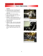
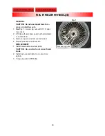
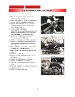
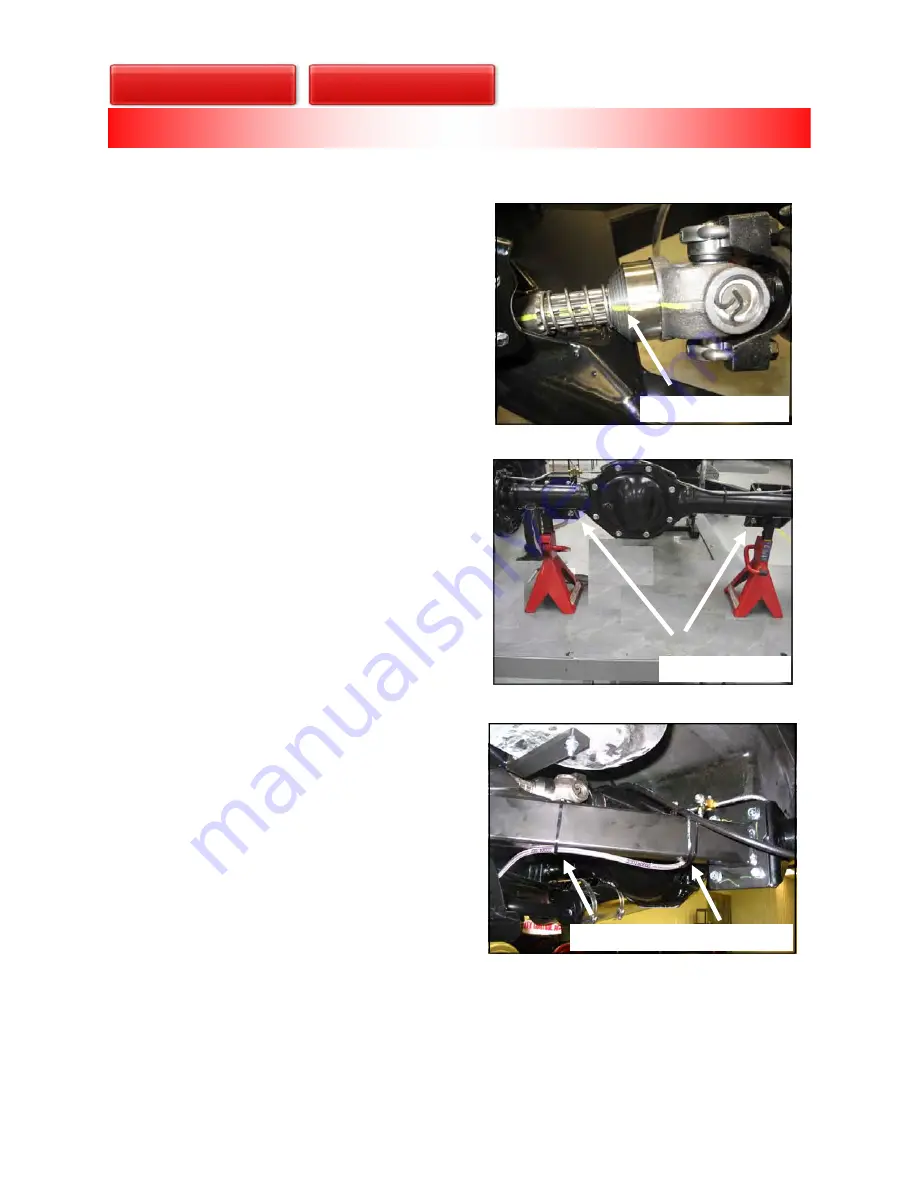
NOTE: See Fig. 1. To ensure proper phas-
ing of driveshaft, mark u-joint and yoke with
a paint marker prior to disassembly.
4. Cut ties securing brake line/cable to swingarm.
5. Remove U-bolts from rear yoke at differential.
6. Use a paint marker to mark a line across differ-
ential and swingarm mounting plates to ensure
side alignment during reassembly.
7.
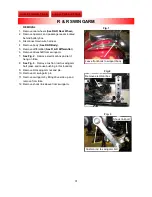
See Fig. 2
. Remove hardware securing differ-
ential to swingarm. Slide differential to rear of
trike allowing U-joint and yoke to be removed
from drive shaft.
8. Remove retaining rings using needle-nose pli-
ers and press existing u-joint from yoke.
REPLACEMENT
1. Install new U-joint into yoke being sure to ori-
ent grease zerk toward front of trike.
2. Replace yoke and U-joint assembly onto end of
driveshaft, ensuring paint marks match be-
tween yoke and drive shaft for proper phasing.
3. Reposition differential so that U-joint and rear
yoke at differential mate together and that paint
marks between differential-to-swingarm mount-
ing plates align.
4. Reinstall diff. hardware; torque to
47 ft.-lbs
.
5. Replace (2) U-bolts, (4) lock washers and nuts;
tighten nuts on both sides of U-joints equally
from side to side and top to bottom; torque to
20 ft.-lbs.
CAUTION: Check differential vent tube to
be sure it is free of any blockage. Blockage
can potentially lead to axle seal failure.
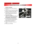
1.
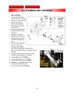
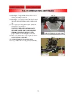
See Fig. 3
. Secure brake lines and cables to
swingarm with new cable ties.
2. Reinstall rear wheels and torque lugs to
75 ft.-
lbs
.
Fig. 2
Fig. 1
Fig. 3
Driveshaft alignment
Remove hardware
Secure brake lines to swingarm
R & R REAR U-JOINT

