background image

LEHR LP5.0 HP Rev.A 2014

44

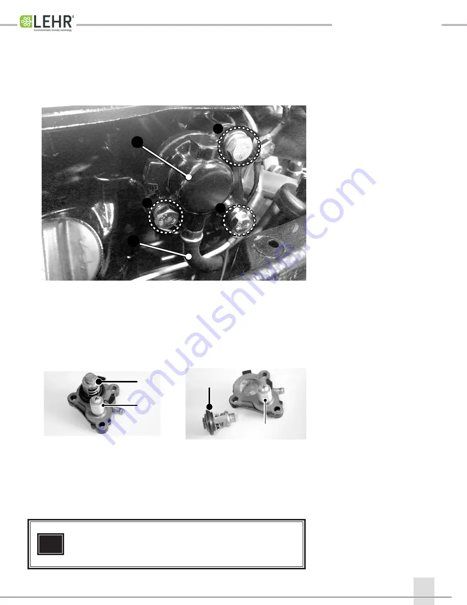
3.  Inspect the anode 

E

 for deterioration and replace if necessary (25% 

or less remaining). Anode deterioration is normal and expected. 


You may clean the anode, but do not paint or apply any coating to 

the anode surface.

4.  Inspect the thermostat and seal for corrosion damage, blockage and 

the seal for cuts. Replace if damaged

5.  To check the thermostat for function, suspend it in a container of 

water and slowly heat the water while monitoring the temperature. 


Check to see if thermostat lifts and opens at the proper temperature 

and clean or replace if necessary.


Thermostat begins to lift at 

48C ~ 52C  (118F ~ 126F) 


and should be fully open to 

3mm  (0.120”) at 60C (140F)

6.  Reassemble with a new gasket and test run for water leaks

D

D

E

E

Water Temperature      Valve Lift

48-52 °C (118-126 °F) 

    0 mm (0 in)

Above 60 °C (140 °F)      above 3 mm (0.12 in)

V

1.  Remove the thermostat housing bolts 

A

, cooling hose 

B

,thermostat 

housing 

C

, and thermostat 

D

.

To Inspect or Replace the Thermostat or Sacrificial Anode 

4

A

A

C

B

A

Summary of Contents for LP 5.0S

Page 1: ...r o p a n e O u t b o a r d E n g i n e Technical Specifications and Step by Step Guides Phone 310 839 9009 Fax 310 943 2172 Email support golehr com Your LEHR Authorized Dealer and Service Provider Call Toll Free 1 877 666 8679 ...

Page 2: ...ev A 2013 Service Manual Table of Contents 1 General Information and Specifications 2 Fuel Systems 3 Ignition 4 Powerhead 5 Gearcase 6 Miscellaneous 7 Parts Book Reference 8 Operators Manual Reference 1 2 3 4 5 6 7 8 ...

Page 3: ...chedule Engine Fastener Torque Specifications General Torque Values Quick Notes Fuel Consumption Chart Special Tools Adjusting Engine Idle Speed Checking the Spark Plug Changing the Engine Oil Changing the Gearcase Oil Lubrication Points Valve Lash Notes 16 18 19 20 21 22 24 17 1 General Information and Specifications 4 3 7 10 11 12 13 15 6 ...

Page 4: ...n take the following precautions BEFORE USE 1 Check cylinder and appliance seals Never use with damaged or missing seals Discard cylinder if dirt or rust particles are in valve area 2 Turn engine off 3 Attach cylinder outdoors away from pilot lights flames sparks or other ignition sources These sources can ignite leaking gas 4 Hand tighten only Never use tools to tighten Overtightening can damage ...

Page 5: ...rting System Ignition control system Ignition timing Spark plug Cooling system Exhaust system Lubrication System 717 mm 28 2 in 361 mm 14 2 in 1 029 mm 40 5 in 1156 mm 45 5 in 381mm 15 0 in 1508 mm 20 in 22 5 kg 49 6 lbs 23 9 kg 52 8 lbs 3 6 kW 5 0 hp at 5 000 r min 4 500 5 500 r min 0 5 gal hr 0 22 gal hr 4 Stroke single cylinder OHV 1 112 cu cm 6 8 cu in 59 mm X 41 mm 2 32 in X 1 61 in 8 7 1 Til...

Page 6: ...ow Water Cruise Angles Drive unit Gear shift positions Gear ratio Reduction gear type Clutch type Propeller shaft type Propeller direction rear view Propeller Diameter X Pitch Propane 110 Octane 4 stroke motor oil 10W 30 SE SF SG SH or SJ API 0 5 L 0 53 US Quarts 17 oz Gear Case Lube 90 100 ml 3 4 oz 4 8 12 16 20 degrees 76 degrees 360 degrees 30 42 54 degrees F N R 2 08 27 13 Straight bevel gear ...

Page 7: ... OUTBOARD MARINE ENGINE MODELS LP5 0S LP5 0L in mm A 14 50 368 B S 22 50 572 B L 27 50 699 C S 17 50 445 C L 22 50 572 D 19 50 495 E 4 25 108 F 12 00 305 G 14 00 356 H 14 00 356 I 2 25 57 J 9 75 248 K 23 50 597 L 13 25 337 M 12 50 318 N 10 50 267 O 13 25 337 P 68 68 O O O M N L ...

Page 8: ...learance 660 kPa 6 6 kgf cm 94 psi 0 1 mm 0 004 in 59 00 59 02 mm 2 323 2 324 in 0 08 mm 0 0031 in 0 05 0 0020 in 58 950 58 965 mm 2 3209 2 3215 in 0 035 0 065 mm 0 0014 0 0026 in 13 009 13 017 mm 0 5122 0 5125 in 12 995 13 000 mm 0 5116 0 5118 in 1 5 mm 0 0382 0 0390 in 2 6 mm 0 0768 0 0846 in 0 10 0 20 mm 0 0059 0 0118 in 0 04 0 08 mm 0 0016 0 0031 in 1 5 mm 0 0461 0 0468 in 2 6 mm 0 0906 0 0984...

Page 9: ...gs Free length Tilt limit 1 87 1 95 mm 0 0736 0 0768 in 2 4 mm 0 0945 in 2 5 mm 0 0024 in 0 2 0 7 mm 0 0008 0 0024 in 26 736 26 836 mm 1 0526 1 0565 in 26 532 26 623 mm 1 0442 1 0481 in 21 950 22 050 mm 0 8642 0 8681 in 14 934 14 984 mm 0 5880 0 5899 in 0 03 mm 0 0012 in 0 08 0 12 mm 0 003 0 005 in 0 08 0 12 mm 0 003 0 005 in 23 9 24 1 mm 0 941 0 949 in 21 9 22 1 mm 0 862 0 870 in 1 84 2 26 mm 0 0...

Page 10: ...0 24 015 mm 0 9449 0 9455 in 0 2 0 6 0 008 0 024 in 0 016 0 046 mm 0 0006 0 0018 in 21 980 21 993 mm 0 8654 0 8659 in 25 95 mm 0 1 022 in 21 0 21 1 mm 0 827 0831 in 0 03 mm 0 0012 in 58 62 C 136 144 F 70 C 158 F 3 mm 0 12 in Ink Stamp Fixed 1950 150 r min Ignition system Ignition timing Ignition spark gap Spark plug cap resistance Ignition Coil unit air gap Ignition Coil unit resistance Primary co...

Page 11: ...m with fresh water CHECKING PAINTED SURFACE OF MOTOR 1 Check the motor for scratches nicks or flaking paint Areas with damaged paint are more likely to corrode If necessary clean and paint the areas NOTE Be sure to turn off the engine when you perform maintenance unless otherwise specified If you or the owner are not familiar with machine servicing this work should be done by your LEHR dealer or o...

Page 12: ...cowling bolt Bottom cowling screw Tiller handle bolt Carrying handle screw Engine shut off switch nut Grease nipple Swivel bracket bolt Throttle grip screw Clamp bracket inner nut Clamp bracket outer nut M7 M7 M8 M8 M8 M8 M6 M6 M6 M6 M5 M8 M8 M6 M6 M8 M6 M6 M6 M6 M6 M5 M6 M6 M5 M8 M6 M6 M5 Item Thread Size Tightening Torques N m 9 0 12 10 22 14 30 6 11 5 0 12 2 0 18 20 44 10 10 18 11 25 13 8 0 8 0...

Page 13: ...tandard fasteners with a standard ISO thread pitch Tightening torque specifications for special components or assemblies are provided in applicable sections for this manual To avoid warpage tighten multi fastener assemblies in a crisscross fashion and progressive stages until the specified torque is reached Unless otherwise specified torque specifications require clean dry threads Components shoul...

Page 14: ...ater level as measured from the water surface to the top of the test tank transom 1950 150 rpm Spark Plug and gap BR6HS 0 5 0 6 mm or 0 020 0 024 in Ignition Coil to Flywheel Air Gap 0 4 0 6 mm or 0 016 0 024 in Valve Lash Performed with cold valves Intake 0 08 0 12 mm 0 003 0 005 in Exhaust 0 08 0 12 mm 0 003 0 005 in Thermostat Temperatures Starts to open at and fully open at 58 62 C 136 144 F 7...

Page 15: ... to read engine Serial Number Code Example LP5 0L 13C00031 LP5 0L 13 C 00031 Model Year Month Engine Number A Lehr Propane 5 0 HP Long Shaft B Year built 2013 C Month built March Month built uses alpha A thru L for Jan thru Dec D Last five digits are production number or 31 A B C D ...

Page 16: ...LEHR LP5 0 HP Rev A 2014 15 1 ...

Page 17: ...meter B Compression Pressure Gauge C Universal Puller D Spark Tester E Inductive Tachometer F Calipers G Paper Clip H Feeler Gauge Assorted Metric Hand Tools I J K L M N A basic assortment of shop equipment and hand tools are all that s required to support basic maintenance activities 1 ...

Page 18: ...l should be approximately 9 from the top of the transom 2 Hook up an inductive tachometer B suitable for a single cylinder four stroke engine Start the engine and allow it to warm up to proper operat ing temperature about 3 minutes 3 Once engine temperature and RPM s are stable use a small screwdriver to adjust the idle speed adjustment screw 1 to attain 1950 150 RPM Turning the screw clockwise wi...

Page 19: ...the spark plug lead securely to the plug The boot should touch the hex of the plug when on all the way 1 Remove the upper engine cover Remove the rubber spark plug boot Remove spark plug by using the spark plug wrench provided in the tool kit the handle of this tool is shaped specifically to access the spark plug Most universal tools will not work Spark Plug BR6HS NGK Spark Plug Gap A 0 5 0 6 mm 0...

Page 20: ...le 5 Install the oil filler cap and then start the engine and warm it up for 5 minutes 6 Turn the engine off and then check the oil level and correct it if necessary Changing the Engine Oil 1 Remove the oil filler cap 2 Place a drain pan under the drain hole and then remove the drain bolt 1 and let the oil drain completely 1 Be sure to clean up any oil spills Engine oil drain bolt 1 18 N m 1 8 kgf...

Page 21: ...would render it ineffective COATING THE BOAT BOTTOM A clean hull improves boat performance The boat bottom should be kept as clean of marine growth as possible If necessary the boat bottom can be coated with an anti fouling paint approved for your area to inhibit marine growth Do not use anti fouling paint which includes copper or graphite These paints can cause more rapid engine corrosion 1 Chang...

Page 22: ...LEHR LP5 0 HP Rev A 2014 21 1 Apply water resistant anit corrosion grease to the areas shown Apply grease to the grease nipple until it flows from the bushings Lubrication Points 1 ...

Page 23: ...ust enough to access the screw behind it Then remove the three lower bolts securing the cover to the engine E 3 Remove the rear propane tank bracket G joining the tank tray to the upper valve cover bolts H by removing bolts F and nuts I 4 Remove the 2 lower valve cover bolts J and rotate the bracket to the fuel line out of the way Remove the valve cover Valve Lash Check Engine must be cold Perform...

Page 24: ... seat the valves rotate the crankshaft two full revolutions returning to TDC Check the valve lash again and adjust if necessary and lock the adjustment check ing to make sure the locking procedure does not change the setting 7 Replace the valve cover gasket and install the valve cover the propane tank sup port bracket and fuel line clip torquing in two steps First torque step is 5 Nm 3 7 ft lbs an...

Page 25: ...LEHR LP5 0 HP Rev A 2014 24 NOTES ...

Page 26: ...2013 25 Propane Fuel Sytem Removing and Replacing the Carburetor Installing the Slide Throttle Cable Cap Adjusting the Idle Speed Removing the Fuel Line Assembly Installing the Fuel Line Assembly Notes 2 26 28 29 30 32 33 ...

Page 27: ...he carburetor and remove the cable C cap D and slide assembly E If the same carburetor will be reinstalled the slide and needle can be retained on the cable If replacing the carburetor always use the new slide that comes with the new carburator 4 To remove the old slide and needle from the throttle cable core wire the small brass retainer pin F in the slide body G must be removed To do so next pag...

Page 28: ...o not fully tighten the carburetor bolts This leaves the carburetor free to move a little while installing the fuel line banjo bolt Always start to thread the banjo bolt by hand until it is finger tight This is an easy thread to cross thread or strip Tighten the carb mounting bolts 8 Nm 6 ft lbs before final torquing the banjo bolt 8 Nm 6 ft lbs When installing a new carburetor always use the slid...

Page 29: ... the idle RPM will be very high since the slide will not return to the proper idle position inside the carburetor Once intalled the pin should be flush with or below the body of the slide Check for security Installing the Slide and Throttle Cable Cap 2 4 To insert the throttle cable and slide assembly into the carburetor be sure the brass cable retainer is facing up Then gently push the slide asse...

Page 30: ... be approximately 9 from the top of the transom 2 Hook up an inductive tachometer B suitable for a single cylinder four stroke engine Start the engine and allow it to warm up to proper oper ating temperature about 3 minutes 3 Once engine temperature and RPM s are stable use a small screw driver to adjust the idle speed adjustment screw 1 to attain 1950 150 RPM in neutral Turning the screw clockwis...

Page 31: ...nt carrying handle on the side closest to the shift handle Flex it away from the cover just enough to access the Phillips head screw behind it It may help to move the shift lever in to forward gear Remove the screw Remove the remaining two screws of this type C from the lower cover 4 Remove the three hex head bolts D that hold the rear lower cover to the engine Remove the cover CONTINUED ON NEXT P...

Page 32: ...se two bolts one at a time pull the clip down and reinstall the bolt otherwise it may disrupt the O ring between the bracket and the crank case resulting in an oil leak 8 Remove the fuel line from the bottom cover by loosening the banjo bolt H with a 16mm wrench and holding the remote connector K with a 10mm deep socket from the hex or 16mm thin wrench on the wrench flats Note the order of the sta...

Page 33: ...n position If both bolts are loose at the same time the O ring may slip out of position and result in an oil leak 4 Install the long banjo bolt through the head of the evaporator and into the carburetor Use a rubber coated banjo washer between the bolt head and the evaporator and be tween the evaporator and carburetor Torque to 8 Nm 6 ft lbs 5 Install the third fuel line clamp G to the valve cover...

Page 34: ...LEHR LP5 0 HP Rev A 2014 33 NOTES ...

Page 35: ...P Rev A 2014 34 Ignition System Ignition System Components and Schematic Checking Ignition Spark Testing Engine Stop Switch Checking Ignition Coil Adjusting or Replacing the Ignition Coil Notes 3 35 36 37 38 39 40 ...

Page 36: ...g flywheel A small electronic circuit board inside the coil controls spark advance 1 Ignition Coil 2 Flywheel 3 Flywheel Magnet 4 Air gap 0 4 0 6 mm 0 016 0 024 in 1 4 2 3 3 Ignition System Schematic ELEC Electrical systems Wiring harness CD Flywheel magnet w B B Black S69M8020 A B C D E W W B B A Flywheel Magnet B Ignition Coil C Spark Plug D Stop Emergency Stop Switch E Ground B Black Wire W Whi...

Page 37: ...e 1 Remove the upper engine cover Remove the spark plug Use the provided spark plug wrench as access to the plug is limited Check the condition of the plug Replace it if rusty or fouled 2 Check the gap Set the gap to 0 5 mm 0 020 in Check for spark by grounding the plug against an unpainted metal surface of the engine and pulling the start rope If spark looks weak testing with a spark tester can t...

Page 38: ...d wire where it is attached to ground on the engine 4 If the results differ from the chart above the stop switch is defective and needs to be replaced Checking the Engine Stop Switch R Continuity YES NO YES ctrical systems t plug cap from the rning the cap coun unit resistance cification e ack B Q 0 S69M8090 Q 0 S69M8100 park plug wire Q Checking the engine shut off switch 1 Check the engine shut ...

Page 39: ...one ohm meter lead to the ignition coil white wire Attach the other ohm meter lead to the ignition coil black wire Record your reading 3 Replace coil if either circuit is out of specification Secondary Spark Plug Wire Resistance Attach one ohm meter lead to the ignition coil white wire Attach the other ohm meter lead to the ignition coil spark plug wire Record your reading Testing the Ignition Coi...

Page 40: ...y 3 If adjusting the coil to fly wheel gap loosen the two coils bolts D and set the gap to 0 4 0 6mm 0 016 0 024 in Torque bolts to 10 Nm 7 ft lbs Recheck the gap on both coil legs to be sure it didn t change while torquing the bolts 4 If replacing disconnect the primary wire and the ground wire and the two attaching bolts D and remove the coil 5 Install the new coil and adjust the flywheel to coi...

Page 41: ...LEHR LP5 0 HP Rev A 2014 40 NOTES ...

Page 42: ...41 Powerhead Checking the Cooling System Cooling System Flow Chart Inspect Replace Thermostat or Sacrificial Anode Replacing the Head Gasket Valve Lash Adjustment Removing and Installing a Powerhead Notes 4 42 43 44 45 49 47 50 ...

Page 43: ...mal on a cold engine as the thermostat is not yet open As the engine warms there should be a steady full stream If no water is present at the thermostat cover nipple and there is no combustion chamber pressure present in the nipple then remove and check the thermostat for debris or damage If thermostat is clean and functioning and and housing is clear of debris it is probable that the water pump n...

Page 44: ... System Flowchart Crankcase Cylinder Block Propane Evaporator Lower Midsection Exhaust Port Idle Exhaust Port Above the Prop Exhaust Outlet Atmosphere Upper Midsection Top Starboard Side Cooling Water Pilot Hole Water Pump Cooling Water Inlet Atmosphere Cylinder Head Thermostat 4 ...

Page 45: ...ontainer of water and slowly heat the water while monitoring the temperature Check to see if thermostat lifts and opens at the proper temperature and clean or replace if necessary Thermostat begins to lift at 48C 52C 118F 126F and should be fully open to 3mm 0 120 at 60C 140F 6 Reassemble with a new gasket and test run for water leaks D D E E Water Temperature Valve Lift 48 52 C 118 126 F 0 mm 0 i...

Page 46: ... install a new head gasket No sealer is necessary 8 Install the cylinder head making sure the rocker arms and pushrods are oiled and properly located and torque the cylinder head bolts in 2 steps Tighten in the order shown M8 Bolts 1 4 Step one torque is 15 Nm 11 ft lb and second step is 30 Nm 22 ft lbs M6 Bolt 5 Step one torque is 6 Nm 4 ft lb and second step is 11 Nm 8 ft lbs 9 Place the rockers...

Page 47: ...t to TDC Top Dead Center as the intake valve closes and stops Both intake and exhaust valves should be completely closed Valves are adjusted cold Adjust both the intake and exhaust valves to specification and lock the adjuster with the lock nut Ensure that the lash clearance does not decrease when you lock the adjuster nut Lock nut torque 7 2ft lbs 10 Nm Next to seat the valves rotate the cranksha...

Page 48: ... enough to access the screw behind it Then remove the three lower bolts screwing the cover to the engine E 3 Remove the rear propane tank bracket G joining the tank trade to the upper valve cover bolts H by removing bolts F and nuts I 4 Remove the 2 lower valve cover retainer bolts J and rotate the bracket to the fuel line out of the way Then remove the valve cover Valve Lash Check Engine must be ...

Page 49: ...que 7 2ft lbs 10 Nm Next to seat the valves rotate the crankshaft two full revolutions returning to TDC Check the valve lash again and adjust if necessary and lock the adjustment check ing to make sure the locking procedure does not change the setting 7 Replace the valve cover gasket and install the valve cover torquing in two steps First torque step is 5 Nm 3 7 ft lbs and the second step is 12 Nm...

Page 50: ...powerhead onto the midsection and secure with the powerhead bolts B Torque to 8 Nm 6 ft lbs 9 Install propane fuel line start in gear protection cable and carburetor slide 10 Test run looking for water or oil leaks Install bottom cowling and the carrying handle POWERUNIT EXPLODED DIAGRAM M6 x 36 mm 8 Nm 0 8 m kg 5 8 ft lb REMOVAL AND INSTALLATION CHART Step Procedure Part name POWER UNIT REMOVAL C...

Page 51: ...LEHR LP5 0 HP Rev A 2014 50 NOTES ...

Page 52: ...rcase Checking Gearcase for Oil and Water Leaks Removing the Gearcase from the Mid Section Gearcase Line Drawing Reference Picture Water Pump Disassembly Installation of Water Pump Installing the Gearcase Notes 5 52 53 54 55 57 56 58 ...

Page 53: ... propeller shaft oils seals fill drain plugs and shift rod boot 3 Relieve the pressure on the tester before removing from the gearcase Check the Gearcase for Leaks 1 1 Check the propeller blades and splines for cracks damage or wear Replace if necessary Checking the Propeller 1 Check the anode for scales grease or oil Clean if necessary Do not oil grease or paint the anode otherwise it will be ine...

Page 54: ...mp 1 Remove the spark plug wire from the spark plug and place the engine in neutral 2 Remove the shift rod connector plug on the exhaust housing and loosen the shift rod connector bolt A 3 Remove the two bolts attaching the gearcase to the midsec tion and remove the gearcase 2 A 5 ...

Page 55: ... r o f 6 4 5 0 6 1 7 4 0 3 2 1 1 B O 1 g n i r a e b 7 4 0 1 0 4 8 4 0 3 S 2 1 1 B O 1 S r e v e l m a c t f i h s 8 4 0 0 2 4 8 4 0 3 L 2 1 1 B O 1 L r e v e l m a c t f i h s 8 4 0 1 1 9 4 0 3 2 1 1 B O 1 n i p p o t s 9 4 LP5 0 LOWER UNIT DRIVE PARTS DWG NO DESCRIPTION Q TY LEHR PART NO MSRP 0 1 1 4 2 0 1 2 1 1 B O 1 0 2 X 6 M t l o b d a e h x e h 1 0 6 0 9 5 0 1 2 1 1 B O 1 m m 6 r e h s a w ...

Page 56: ... to the gearcase 2 Slide the pump housing up the shaft noting the condition and assembly order of the water pump parts 3 Inspect and replace worn parts A Shift Rod B Gasket C Water Pipe Seal D Dowel Pins E Impeller Drive Pin F Bolts G Stainless Steel Plate H Impeller I Impeller Cup J Impeller Pump Housing J B I H E G 5 Water Pump Disassembly F D C ...

Page 57: ...nt the cup tab extension into the recess in the impeller housing 5 Slide the housing over the driveshaft Align the impeller housing with the water pump impeller and push the housing down onto the impeller while rotating the driveshaft in a clockwise direction until it is completely seated against the stainless steel plate 6 Install the 4 impeller housing bolts and tighten 7 Install gearcase onto m...

Page 58: ... i r p a n s 0 4 0 4 9 2 1 4 0 3 2 1 1 B O 1 r a e g g n i v i r d 1 4 5 1 3 2 4 0 3 2 1 1 B O 1 m i h s r a e g g n i v i r d 2 4 0 0 5 1 1 3 4 0 3 S 2 1 1 B O 1 S t f a h s e v i r d 3 4 0 0 8 1 1 3 4 0 3 L 2 1 1 B O 1 L t f a h s e v i r d 3 4 0 0 3 4 4 0 3 2 1 1 B O 1 n i p r e l l e p m i 4 4 0 6 0 5 4 0 3 2 1 1 B O 1 p i l c r i c 5 4 0 5 8 8 6 4 0 3 2 1 1 B O 1 r a e g d r a w r o f 6 4 5 0...

Page 59: ...LEHR LP5 0 HP Rev A 2014 58 NOTES ...

Page 60: ...e Bottle Bracket Removing the Engine Rear Lower Cover Rubber Bushing Installation Throttle Cable Installation Tiller Handle Reference Picture Steering Friction Screw Installation Manual Starter Adjusting Start in Gear Protection Notes 6 60 61 62 62 63 64 65 66 64 ...

Page 61: ...racket has three bolts and nuts retaining it to support brackets Loosen the bolts and remove them one at a time along with the washers Note there is a spacer bushing located underneath the bolt 3 3 Swing the fuel line and bottle bracket out of the way and secure Removing the Bottle Bracket 6 1 2 3 ...

Page 62: ... 4 bolts A that retains the rear carrying handle and flex the handle open to remove it 3 Remove two bolts B from the front carrying handle closest to the shift handle Flex it away from the cover just enough to access the Phillips head screw behind it It may help to move the shifter lever in to forward gear Remove the screw Remove the remaining two screws of this type C from the lower cover 4 Remov...

Page 63: ... fit it into the steering bracket 4 After fitting it check that there is no clearance between the bushing flange and the steering bracket end C 1 To install the tiller end of the throttle cable insert the cable and into slot A in the stainless steel plate from the inside of the lower covers There are two holes side by side inside the tiller arm One hole is a through hole large enough to allow the ...

Page 64: ... 7 0 1 0 6 2 1 1 B O 1 e l d n a h r e l l i t 0 1 0 0 1 1 1 0 6 2 1 1 B O 1 w e r c s d a e h s p i l l i h p l a v o 1 1 0 1 5 1 2 1 0 6 2 1 1 B O 1 p i r g 2 1 5 3 1 3 3 1 0 6 2 1 1 B O 1 e l d n a h e l t t o r h t 3 1 0 9 0 4 1 0 6 2 1 1 B O 1 6 2 T S w e r c s g n i p p a t d a e h n a p s p i l l i h p 4 1 0 6 7 5 1 0 6 2 1 1 B O 1 d n a b r o t a c i d n i 5 1 0 0 1 6 1 0 6 2 1 1 B O 1 0 1...

Page 65: ... a then install the swivel bra tighten the friction screw Steering Friction Screw Installation 1 Grease the threads of the friction screw 4 2 Insert the screw into the hole in the pivot tube casting 2 and completely through both holes in the internal band clamp 1 It may take some wig gling to get the end of the screw to enter both holes in the clamp 3 Continue to push the screw in while turning to...

Page 66: ...the brack et assembly Remove bolts and nuts from position 1 and 2 and loosen bolt 3 Rotate the bottle bracket to expose the starter assembly bolt 2 Remove the three bolts B that secure the starter assembly Loosen the lock nut that holds the start in gear protection cable Remove the cable then remove the starter assembly 1 2 3 B B B 3 ...

Page 67: ...on cable C so that the pointer on the lever A aligns with the arrow on the starter B 3 Test the operation to be sure the start rope is locked when latched firmly in forward or reverse gear but pulls freely with no noise in neutral Tighten lock nuts once adjustment is confirmed good 6 C A A B B INCORRECT ADJUSTMENT CORRECT ADJUSTMENT ...

Page 68: ...LEHR LP5 0 HP Rev A 2014 67 NOTES 6 ...

Page 69: ...LEHR LP5 0 HP Rev A 2014 68 DETAILED PARTS LIST AND DIAGRAMS MODELS LP5 0S LP5 0L ...

Page 70: ...LEHR LP5 0 HP Rev A 2014 69 7 LP5 0 LOWER UNIT PARTS 1 2 3 4 5 6 7 8 9 10 11 12 13 14 15 16 17 19 20 21 22 26 25 24 18 23 ...

Page 71: ... k c a r b t f i h s r a e g 1 1 0 7 0 2 1 0 7 2 1 1 B O 1 5 M r e h s a w 2 1 0 1 1 3 1 0 7 2 1 1 B O 1 5 2 5 M t l o b d a e h x e h 3 1 0 5 3 1 4 1 0 7 2 1 1 B O 1 d o r g n i t c e n n o c t f i h s 4 1 0 7 0 5 1 0 7 2 1 1 B O 1 5 M r e h s a w 5 1 0 9 0 6 1 0 7 2 1 1 B O 1 2 1 6 1 n i p r e t t o c 6 1 0 2 1 7 1 0 7 2 1 1 B O 1 t e m m o r g e p i p r e t a w 7 1 0 0 4 8 1 0 7 2 1 1 B O 1 p i...

Page 72: ...2014 71 7 LP5 0 LOWER UNIT DRIVE COMPONENTS 1 2 3 4 5 6 7 8 9 10 11 12 13 14 15 16 17 18 19 20 21 22 23 24 25 26 28 29 30 31 32 33 34 35 36 37 38 39 40 41 42 43 44 45 46 47 48 49 50 51 52 53 54 57 56 55 56 58 55 60 59 27 6 ...

Page 73: ...b d a e h x e h 9 2 0 5 9 3 0 3 0 3 2 1 1 B O 1 r e v o c e v i r d t i n u r e w o l 0 3 0 0 6 1 3 0 3 2 1 1 B O 1 e v i r d t i n u r e w o l g n i r O 1 3 0 1 3 2 3 0 3 2 1 1 B O 2 r e h s a w r a e g e s r e v e r 2 3 0 5 8 8 3 3 0 3 2 1 1 B O 1 r a e g e s r e v e r 3 3 0 2 6 1 4 3 0 3 2 1 1 B O 1 g n i r a e b 4 3 5 2 5 5 3 0 3 2 1 1 B O 2 t f a h s e v i r d l a e s l i o 5 3 0 5 5 6 3 0 3 ...

Page 74: ...LEHR LP5 0 HP Rev A 2014 73 7 LP5 0 STEERING PARTS 24 23 21 22 20 19 18 17 16 15 14 11 13 12 1 2 3 4 5 6 7 8 9 10 7 ...

Page 75: ...n a h r e l l i t 0 1 0 0 1 1 1 0 6 2 1 1 B O 1 w e r c s d a e h s p i l l i h p l a v o 1 1 0 1 5 1 2 1 0 6 2 1 1 B O 1 p i r g 2 1 5 3 1 3 3 1 0 6 2 1 1 B O 1 e l d n a h e l t t o r h t 3 1 0 9 0 4 1 0 6 2 1 1 B O 1 6 2 T S w e r c s g n i p p a t d a e h n a p s p i l l i h p 4 1 0 6 7 5 1 0 6 2 1 1 B O 1 d n a b r o t a c i d n i 5 1 0 0 1 6 1 0 6 2 1 1 B O 1 0 1 M r e h s a w 6 1 5 2 4 7 1 ...

Page 76: ...LEHR LP5 0 HP Rev A 2014 75 7 LP5 0 CLAMP PARTS 31 32 33 34 35 36 37 1 2 3 4 5 6 7 8 9 11 12 13 14 15 10 16 26 25 21 22 20 15 19 27 28 29 30 4 15 15 15 20 18 24 23 17 26 25 38 ...

Page 77: ...2 1 1 B O 2 0 2 X 6 M t l o b d a e h x e h 8 1 5 2 9 9 1 0 4 2 1 1 B O 1 t e k c a r b e l b a t s u j d a e t a l p r e d n i b 9 1 0 2 7 0 2 0 4 2 1 1 B O 2 g n i h s u b t i l p s 0 2 0 7 4 1 2 0 4 2 1 1 B O 1 B g n i r p s l a n o i s r o t 1 2 5 0 5 2 2 2 0 4 2 1 1 B O 1 r e v e l t l i t 2 2 0 7 4 3 2 0 4 2 1 1 B O 1 A g n i r p s l a n o i s r o t 3 2 0 0 5 4 2 0 4 2 1 1 B O 1 e l d n a h ...

Page 78: ...3 34 35 55 65 44 43 52 21 22 23 24 25 26 27 28 29 30 11 12 13 14 15 16 17 18 19 20 1 5 6 7 8 9 10 9 64 67 66 53 54 46 47 48 49 50 75 76 75 45 75 37 41 36 38 42 59 40 61 62 63 68 69 71 72 73 74 39 59 72 4 59 79 3 77 84 82 71 71 85 86 87 81 80 77 78 78 77 83 83 2 59 60 70 ...

Page 79: ... 6 M t l o b d a e h x e h 4 2 0 2 3 5 2 0 1 2 1 1 B O 1 l l i f l i o g n i r O 5 2 26 oil fill cap dipstick 0 0 2 1 6 2 0 1 2 1 1 B O 1 0 4 8 1 7 2 0 1 2 1 1 B O 1 t e k s a g d a e h 7 2 5 2 5 7 1 8 2 0 1 2 1 1 B O 1 d a e h r e d n i l y c 8 2 5 2 0 3 9 2 0 1 2 1 1 B O 2 e d i u g e v l a v 9 2 0 1 2 1 0 3 0 1 2 1 1 B O 1 t e k s a g r e v o c e v l a v 0 3 5 3 6 1 1 3 0 1 2 1 1 B O 1 r e v o ...

Page 80: ... h x e h 6 6 0 1 1 4 2 0 1 2 1 1 B O 1 0 2 X 6 M t l o b d a e h x e h 7 6 0 9 8 1 8 6 0 1 2 1 1 B O 1 t e k c a r b e l t t o b 8 6 69 band clamp assembly 0 1 9 1 9 6 0 1 2 1 1 B O 1 70 fuel line assembly 0 5 3 5 0 7 0 1 2 1 1 B O 1 0 0 1 1 7 0 1 2 1 1 B O 4 m m 0 1 s p m a l c e s o h 1 7 0 9 0 2 7 0 1 2 1 1 B O 2 m m 5 s p m a l c e s o h 2 7 0 0 3 3 7 0 1 2 1 1 B O 1 m m 0 5 2 X m m 0 1 e s o ...

Page 81: ... i r p s e v l a v 4 5 1 4 0 9 0 1 2 1 1 B O 2 l a e s l i o e v l a v 5 0 9 6 1 9 0 1 2 1 1 B O 2 g n i r p s e v l a v 6 0 0 3 2 9 0 1 2 1 1 B O 2 r e n i a t e r g n i r p s e v l a v 7 0 9 0 3 9 0 1 2 1 1 B O 2 r e p e e k k c o l e v l a v 8 5 9 9 4 9 0 1 2 1 1 B O 2 m r a r e k c o r 9 0 5 4 5 9 0 1 2 1 1 B O 2 t a e s l l a b m r a k c o r 0 1 0 5 2 6 9 0 1 2 1 1 B O 2 t u n n o g a x e h 1...

Page 82: ...3 connecting rod assembly 0 5 8 5 3 0 1 1 2 1 1 B O 1 4 woodruff key 0 2 4 4 0 1 1 2 1 1 B O 1 5 piston pin 0 5 7 5 0 1 1 2 1 1 B O 1 6 piston pin retainer 0 0 1 6 0 1 1 2 1 1 B O 2 5 2 0 8 7 0 1 1 2 1 1 B O 1 n o t s i p 7 0 5 1 1 8 0 1 1 2 1 1 B O 1 g n i r l i o 8 0 5 1 1 9 0 1 1 2 1 1 B O 1 g n i r p s n o i s s e r p m o c d n 2 9 0 5 1 1 0 1 1 1 2 1 1 B O 1 g n i r n o i s s e r p m o c p o ...

Page 83: ... 1 m m 6 r e h s a w 4 0 8 0 5 0 0 5 2 1 1 B O 8 l e w o d 5 0 5 3 5 6 0 0 5 2 1 1 B O 1 e l d n a h d r a w r o f 6 5 2 1 5 7 0 0 5 2 1 1 B O 1 e l d n a h d r a w k c a b 7 0 0 6 8 0 0 5 2 1 1 B O 1 B p i r t s g n i l a e s 8 0 0 6 9 0 0 5 2 1 1 B O 1 A p i r t s g n i l a e s 9 0 8 0 0 1 0 5 2 1 1 B O 3 w e r c s d a e h t a l f k n u s r e t n u o c 0 1 0 1 1 1 1 0 5 2 1 1 B O 3 t r e s n i w...

Page 84: ...1 1 2 1 1 B O 1 l e e h w g n i t r a t s 9 0 5 7 1 2 1 1 2 1 1 B O 1 e d i u g e p o r g n i t r a t s 0 1 0 0 9 2 2 1 1 2 1 1 B O 1 l a e s 1 1 0 5 9 3 2 1 1 2 1 1 B O 2 e l d n a h g n i t r a t s 2 1 5 2 1 4 2 1 1 2 1 1 B O 1 e l d n a h r e v o c 3 1 0 0 2 5 2 1 1 2 1 1 B O 2 m r a g n i t a u t c a g n i r p s 4 1 0 2 3 6 2 1 1 2 1 1 B O 2 l w a p g n i v i r d 5 1 0 0 2 7 2 1 1 2 1 1 B O 1 ...

Page 85: ... B O 1 l a u n a m s r o t a r e p o 1 9 9 3 1 0 1 K P L 2 0 0 8 2 1 1 B O 1 d r a y n a l h c t i w s p o t s e n i g n e 2 5 2 0 2 0 5 T P L 3 0 0 8 2 1 1 B O 1 h c u o p t i k l o o t 3 0 0 5 4 0 0 8 2 1 1 B O 1 e l d n a h d n a e p o r r e t r a t s y c n e g r e m e 4 5 4 ft propane connector hose 1 9 9 9 2 4 H P L 6 0 8 2 1 1 0 B O ...

Page 86: ...AUTION BEFORE OPERATING THIS PRODUCT READ AND FOLLOW ALL SAFETY RULES AND OPERATING INSTRUCTIONS THIS PRODUCT CONTAINS CHEMICALS KNOWN TO THE STATE OF CALIFORNIA TO CAUSE CANCER BIRTH DEFECTS OR OTHER REPRODUCTIVE HARM WARNING Important Manual Information 1 General Information 2 Installation 7 Operation 8 Maintenance 13 Troubleshooting 21 Specifications 24 Warranty 25 ...

Page 87: ...operate a unit that has a suspected leak Always remove the propane canister from any unit that has a suspected leak Green Key is a trademark of the Coleman company WARNING PROPANE IS HIGHLY FLAMMABLE AND ITS VAPORS CAN EXPLODE IF IGNITED SAFETY WARNINGS FOR PROPANE UNITS CARBON MONOXIDE HAZARD Burning propane makes Carbon Monoxide CO CO is invisible has no smell and can kill you Operating your out...

Page 88: ... your LEHR dealer or call 1 866 941 LEHR 5347 WARNING Warning symbol indicates ATTENTION YOUR SAFETY IS INVOLVED Failure to follow WARNING instructions could result in severe injury or death to the machine operator a bystander or a person inspecting or repairing the outboard motor NOTE A NOTE provides information to make procedures easier or clearer To ensure long product life LEHR recommends that...

Page 89: ... which contain carbon monoxide a colorless odorless gas which may cause brain damage or death when inhaled Symptoms include nausea dizziness and drowsiness Keep cockpit and cabin areas well ventilated Avoid blocking exhaust outlets Check throttle shift and steering for proper operation before starting the engine Attach the engine stop switch lanyard cord to a secure place on your clothing or your ...

Page 90: ... 8 TRIM ROD 9 CLAMP BRACKET 10 THROTTLE FRICTION ADJUSTER 11 THROTTLE LEVER TILLER HANDLE 12 BOTTLE BRACKET CLAMP 13 PULL START HANDLE 14 ENGINE SHUT OFF SWITCH 15 REMOTE PROPANE CONNECTOR 16 CLAMP SCREWS 17 ROPE ATTACHMENT 18 GEAR SHIFT LEVER 19 13 14 15 16 17 9 12 10 The outboard motor serial number is stamped on the label attached to the clamp bracket Record your outboard motor serial number yo...

Page 91: ...hift positions to provide operation Forward F Neutral N and Reverse R Reduce throttle speed to idle speed Always shift outboard into gear with a quick motion THROTTLE GRIP The throttle grip is on the tiller handle Turn the grip counterclockwise to increase speed and clockwise to decrease speed THROTTLE FRICTION ADJUSTER A friction device provides adjustable resistance to movement of the throttle g...

Page 92: ...oning Avoid accidentally pulling the lanyard during normal operation Loss of engine power means the loss of most steering control Also without engine power the boat could slow rapidly This could cause people and objects in the boat to be thrown forward NOTE The engine cannot be started with the stop switch lock removed ENGINE STOP BUTTON To stop the engine push and hold this button or pull the lan...

Page 93: ...ll the way up lift up on the lock lever to disengage it while lowering the engine WARNING Do not use the tilt support bar when trailering the boat The outboard motor could shake loose from the tilt support and fall If the motor cannot be trailered in the normal running position use an additional support device to secure it in the tilt position TOP COVER LOCK LEVER To remove the engine top cover re...

Page 94: ...ncy the water resistance drag of the boat and outboard motor must be made as little as possible The mounting height of the outboard motor greatly affects the water resistance If the mounting height is too high cavitation tends to occur thus reducing the propulsion and if the propeller tips cut the air the engine speed will rise abnormally and cause the engine to over heat If the mounting height is...

Page 95: ...elow the lower mark or drain to the specified level if it is above the upper mark Recommended engine oil 4 stroke motor oil with a combination of the following SAE and API oil classifications Engine oil type SAE 10W 30 Engine oil grade API SE S F SG SH SJ SL Engine oil quantity 0 53USqt 0 5L WARNING ALL ENGINES ARE SHIPPED FROM THE FACTORY WITHOUT ENGINE OIL ADD OIL BEFORE STARTING ENGINE FUEL Che...

Page 96: ...e canister clamp pull the canister out and remove the propane connector by turning it counterclockwise 3 Remove the empty canister 4 Dispose of empty propane canisters in accordance to Federal State and Local regulations CONNECTING REMOTE PROPANE TANK 1 Make sure the engine is off and the propane tank is closed 2 Connect the remote hose to the remote propane tank Use only a high pressure propane h...

Page 97: ...istance Then give a strong pull straight out to start the engine Repeat if necessary 5 After the engine starts slowly return the manual starter handle to the original position before releasing it 6 Slowly return the throttle grip to the fully closed position NOTE If the engine fails to start after 4 or 5 tries open the throttle a small amount between 1 8 1 4 throttle and try again Also if the engi...

Page 98: ...de the desired hole To raise the bow trim out move the trim rod away from the transom To lower the bow trim in move the trim rod closer to the transom Test the boat with the trim set to different angles to find the position that works best for your boat and operating conditions NOTE The outboard motor trim angle can be changed approximately 4 degrees by shifting the trim rod one hole When the boat...

Page 99: ...e OPERATION PROCEDURE FOR TILTING UP 1 Place the gear shifter lever in neutral and face the outboard motor forward 2 Tighten the steering friction adjuster by turning it clockwise to prevent the motor from turning freely 3 Hold the carrying handle and tilt the engine up fully until the tilt support lever automatically locks PROCEDURE FOR TILTING DOWN 1 Slightly tilt the outboard motor up 2 Slowly ...

Page 100: ... outboard motor accidentally falls Do not use the tilt support lever when trailering the boat The outboard motor could shake loose from the tilt support and fall If the motor can not be trailered in the normal running position use an additional support device to secure it in the tilt position The outboard motor should be trailered and stored in the normal running position If there is insufficient ...

Page 101: ...ter each use before being stored Do not run the engine without supplying it with cooling water Either the engine water pump will be damaged or the engine will be damaged from overheating Before starting the engine be sure to supply water to the cooling water passages 1 Wash the outboard motor body using fresh water 2 Remove the engine top cover 3 Install the outboard motor on a test tank or submer...

Page 102: ...cooling system with fresh water CHECKING PAINTED SURFACE OF MOTOR 1 Check the motor for scratches nicks or flaking paint Areas with damaged paint are more likely to corrode If necessary clean and paint the areas NOTE Be sure to turn off the engine when you perform maintenance unless otherwise specified If you or the owner are not familiar with machine servicing this work should be done by your LEH...

Page 103: ...g ID mark i e NGK Standard spark plug BR6H8 Spark plug Boot INSPECTION CHECKPOINTS Periodically check the fuel system for leaks With the propane tank attached and the engine cover removed inspect the following fuel system parts for leakage Leaks can be identified by smell of propane or carefully listening for a hissing sound of escaping gas Suspected leaks can be verified by applying soapy water s...

Page 104: ...tor is upright not tilted when checking and changing the engine oil If the oil level is above the upper level mark drain until the level meets the specified capacity Overfilling the oil could cause leakage or damage Change the engine oil after the first 10 hours of operation and every 100 hours or at 6 month intervals thereafter Otherwise the engine will wear quickly NOTE Change the engine oil whe...

Page 105: ... spark plug Also place the shift control in neutral and remove the lanyard from the engine stop switch Check each of the propeller blades for wear erosion from cavitation or other damage Check the propeller shaft for damage Check the splines for wear or damage Check for fish line tangled around the propeller shaft Check the propeller shaft oil seal for damage REMOVING THE PROPELLER 1 Straighten th...

Page 106: ... the propeller from turning PROPELLER SELECTION Your LEHR outboard engine is supplied with a propeller that matches the needs of a boat most suited to an engine of its size If you feel you are not getting optimal performance from the engine on your boat a different pitch propeller could help The performance of your outboard motor will be affected if you choose a different propeller as an incorrect...

Page 107: ...e used oil after it has been drained If the oil is milky water is getting into the gear case which can cause gear and bearing damage Consult your LEHR dealer for repair of the lower unit seals 5 With the outboard motor in a vertical position and using a flexible or pressurized filling device inject the gear oil into the gear oil drain screw hole 6 When the oil begins to flow out of the oil level p...

Page 108: ...ssible faulty internal engine parts A Have serviced by a LEHR dealer ENGINE IDLES IRREGULARLY OR STALLS Q Is propane tank empty A Check tank fluid level by shaking it Q Is spark plug fouled or incorrect type or gap A Inspect spark plug Clean or replace with recommended type Q Is the Idle speed set correctly A Adjust Idle screw or have serviced by LEHR dealer Q Are fuel joints connected correctly A...

Page 109: ...damage is found or not return to the nearest harbor slowly and carefully 4 Have the outboard motor inspected before operating it again STARTER WILL NOT OPERATE If the start mechanism does not operate the engine cannot be cranked with the starter the engine can be started with an emergency starter rope WARNING Use this procedure only in an emergency and only to return to the port for repairs Make s...

Page 110: ...cessary PROCEDURE FOR SUBMERGED MOTOR If the outboard motor has been submerged immediately take it to a LEHR dealer Some corrosion may begin almost immediately If you cannot immediately take the outboard to a dealer follow the procedures below in order to minimize engine damage 1 Wash away mud salt seaweed and debris with fresh water 2 Remove the spark plug then face the spark plug hole downward t...

Page 111: ...HEIGHT 15 381 mm S 20 508 mm L MAX OPERATING R P M 4000 4500 R P M IDLE SPEED 2000 R P M IGNITION TYPE ELECTRONIC IGNITION SWITCH TETHER VALVE CLEARANCE IN and EX COLD SPARK PLUG GAP 0 020 0 024 INCH 0 5 0 6 mm LUBRICATION CRANKCASE OIL CAPACITY 0 53 US qt 0 5L FUEL STARTER PULL CHORD AUTO REWIND 003 005 in 0 08 0 12mm PROPANE 4 STROKE 10W 30 SPARK PLUG TORQUE SPEC 18 4 ft lb 25 0 N m GEAR OIL CAP...

Page 112: ...gation to any purchaser HOW TO OBTAIN SERVICE Warranty service is available with proof of purchase through your local authorized service dealer To locate the dealer in your area visit our website at www golehr com or call 1 866 941 LEHR or write to 8922 Ellis Ave LA CA 90034 CALIFORNIA EMISSIONS EPA CONTROL WARRANTY STATEMENT YOUR WARRANTY RIGHTS AND OBLIGATIONS The California Air Resources Board ...

Page 113: ...nted part that is scheduled only for regular inspection in the written instructions required by Subsection d must be warranted for the warranty period defined in Subsection b 2 A statement in such written instructions to the effect of repair or replace as necessary will not reduce the period of warranty coverage Any such part repaired or replaced under warranty must be warranted for the remaining ...

Page 114: ...LEHR LP5 0 HP Rev A 2014 113 8 NOTES ...

Page 115: ...engine 2004 exhaust emission standards Engines meeting these standards have 20 lower emissions than One Star Low Emission engines Three Stars Ultra Low Emission The three star label identifies engines that meet the Air Resources Board s Personal Watercraft and Outboard marine engine 2008 exhaust emission standards or the Sterndrive and Inboard marine engine 2003 exhaust emission standards Engines ...

Reviews: