background image

Summary of Contents for ST 025CS

Page 1: ...chments Starting Stopping Operation Maintenance Cleaning and Storage Troubleshooting Speci _cations Warranty 2 3 4 5 6 7 8 9 10 11 t2 19 19 20 2t ECO TRIMMER MODELS ST 025SS ST 025DC ST 025CS ST 025DS DO NOT RETURN THE UNIT TO THE RETAILER Call 1 866 941 LEHR 5347 WARNING I THE ENGINE EXHAUST FROM THfS PRODUCT CONTA1NS CHEMICALS KNOWN TO THE STATE OF CALIFORNIA TO CAUSE CANCER BIRTH DEFECTS OR OTH...

Page 2: ...READ ALL INSTRUCTION BEFORE OPERATING Inspect the unit before use Replace damaged parts Check for fuel leaks Make sure all fasteners are in place and secure Replace parts that are cracked chipped or damaged in any way Do not operate the unit with loose or damaged parts Carefully inspect the area before starting the uniL Remove all debris and hard or sharp objects such as glass wire etc Be aware of...

Page 3: ...ousing or muffler These parts get extremely hot from operation even after the unit is turned off Do not operate the engine faster than the speed needed to cut trim or edge Do not run the engine at high speed when not cutting Always stop the engine when cutting is delayed or when walking from one cutting location to another If you strike or become entangled with a foreign object stop the engine imm...

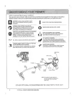
Page 4: ...ng this unit Use a full face shield when needed OIL Refer to operator s manual for the proper type of oil THROWN OBJECTS AND ROTATING CUTTER CAN CAUSE SEVERE INJURY WARNING Do not operate without the cutting attachment shield tn place Keep away from the rotating cutting attachment ON OFF STOP CONTROL OFF or STOP KEEP SYSTANDERS AWAY WARNING Keep all bystanders especially children and pets at least...

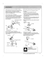
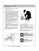
Page 5: ... the handle parts evenly over the rubber sleeve on shaft Do not completely tighten 3 While holding the unit in the operating position Fig 14 position the D handle to the location that pro vides you the best grip Tighten the clamp screws evenly until the D Handle is secure_ Attaching Screws _ I f _ __ D Handle Washer Attaching Screws Fig FOR STRAIGHT SHAFT TRIMMERS Place the cutting attachment shie...

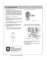
Page 6: ... to measure the correct amount during future oil changes See Changing The Oil p 13 t Unscrew the top of the bottle ofoil and remove the seal covering the opening_ Replace the top Fig S Fig S 2 Place the unit on a level surface fig 6 Fig 6 3 Remove the oil plug I dipstick from the crankcase FigoT 4 Pour the entire bottle ofoil into the oil fill hole Fig 7 Fig 7 oil Fill Hole Check oil before each u...

Page 7: ...nt 49 U S_C S124 _ 6oNever put in luggage or take on trains or aircraft 7_To discard contact local refuse hauler or recycle ten ter Never put in fire or incinerator Do not puncture If your cylinder was purchased with a Green Key or similar device install it when empty and cylinder may be recycled with other steel items NOTE FIRE EXPLOSIONHAZARD Contains enough gas to cause serious fire explosion a...

Page 8: ...g screwed ino Make sure that the connector is installed tight enough that any leakage stops Hand tight is sufficient Slide canister back so all of fue_ line components are behind the guard and latch the canister clamp REMOVING THE PROPANE CANISTER 1oMake sure the engine is off 2 Un latch the bottle clamp and push canister against the guard exposing the propnae connector Remove the propane connecto...

Page 9: ...ING ATTACHMENTS OR ADD ONS t Turn the knob counterclockwise to loosen Fig 12 2 Pressand hold the release button Fig 12 3 While firmly holding the upper shaft housing pull the cutting attachment or add on straight out of the coupler Fig 12 _ Coupler ReleaseButton Fig t2 Turn the knob clockwise to tighten Fig 1I Unit is ready to use 4 For edging when usingthe string trimmer head cut ting attachment ...

Page 10: ...for1S to30seconds Incold weather move thethrottle slowly until theengine warms upfor30to 60seconds NOTE When starting theengine invery hotorcold conditions itmay benecessary tosqueeze the throttle open while pulling thestarter rope Fig 14 STOPPING INSTRUCTIONS 1 Release your hand from the throttle control Allow the engine to cool down by idling 2 If your unit is equipped with a spring loaded ON OF...

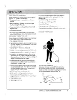
Page 11: ...alls Cutting with more than the tip will reduce cutting ef fidency and may overload the engine Cut grass over 8 inches 200 mm by working from top to bottom in small increments to avoid prema ture line wear or engine drag Slowly move the trimmer into and out of the cutting area at the desired height Move either in a forward backward or side to side motion Cutting shorter lengths produces the best r...

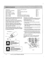
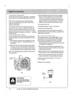
Page 12: ... level in the crankcase cannot be overemphasized Check oil before each use 1 Stop the engine and allow to cool 2 Placethe unit on a fiat level surface to get a proper oil level reading 3 Keep dirt grass clippings and other debris out of the engine Clean the area around the oil fill plug dipstick before removing it 4 Remove the oil fill plug dipstick and wipe off oil Rein sert it all the way back i...

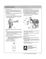
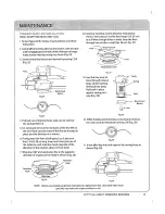
Page 13: ...ick 7 Reconnect the spark plug boot CLEANING THE AIR FILTER Clean and re oil the air filter every 10 hours of operation tt is an important item to maintain Failure to maintain your air filter properly can result in poor performance or can cause permanent damage to your engine 1 Remove phillips head screw in air filter coveroThen pull the air filter cover out and upwards Fig 21 2 Remove the air fil...

Page 14: ...e idles turn the idle speed screw counterclock_wise 1 8 of a turn at a time as needed to reduce idle speed Checking the fuel cleaning the air filter and adjusting the idle speed should solve most engine problems If not and all of the following are true the engine will not idle the engine hesitates or stalls on acceleration there is a loss of engine power Check the spark plug for proper gap and con...

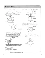
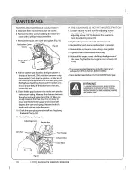
Page 15: ...e Fig_28 Fig 25 4 Pull reel out of trimmer body take care to not lose the spring behind it 5_Un wind and remove the remnants of the line left on the reelo Note how the ends of the line are hooked in place and the direction it is wound If using new line from a bulk spool cut 2 pieces of line 7 5ft 2 28 m long Insert each line into one of the holes on each retention hook opposite of the direction of...

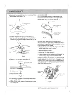
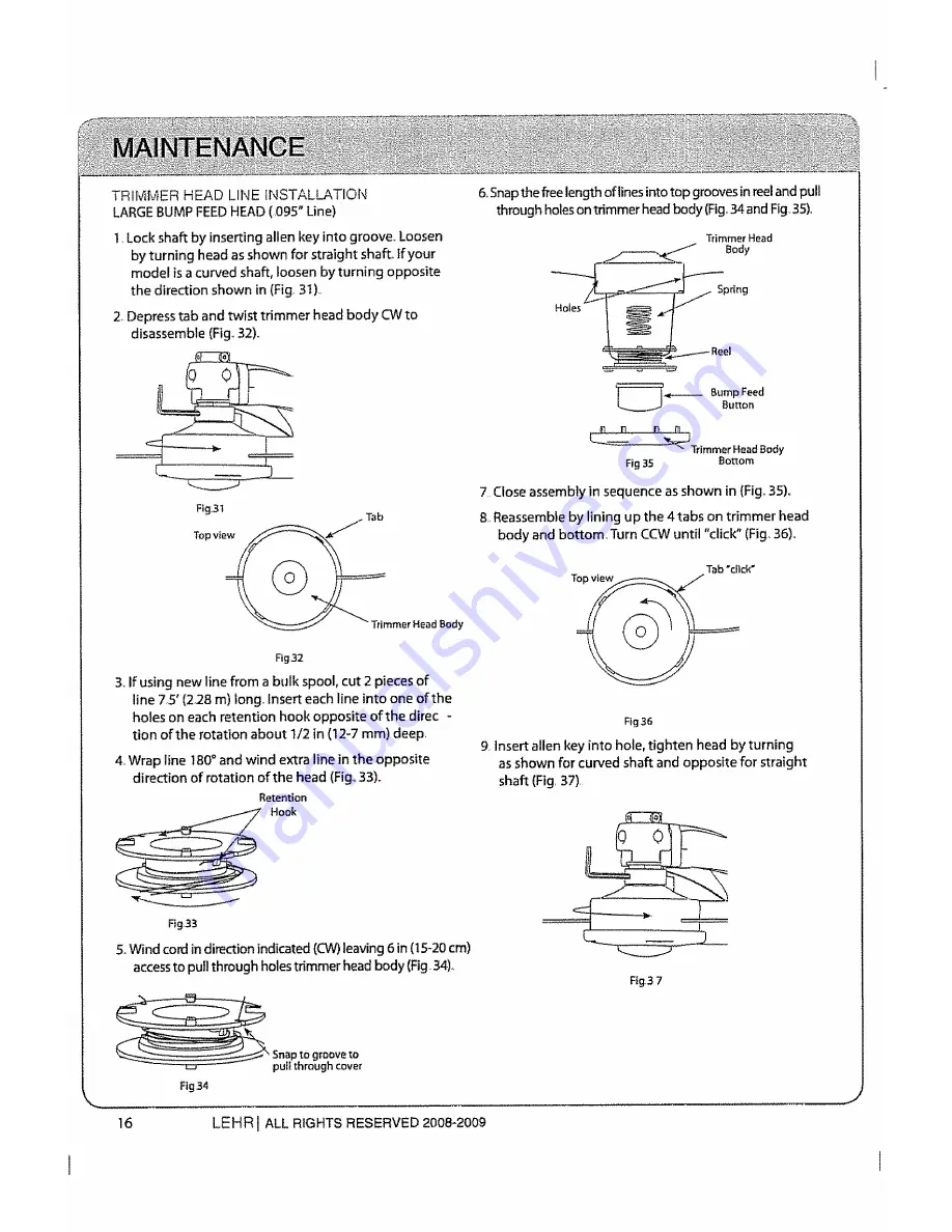
Page 16: ...m deep 4oWrap line 80 and wind extra line in the opposite direction of rotation of the head Fig_33 Retention Hook 6oSnapthe free length of linesinto top grooves in reel and pull through holeson trimmer head body Fig 34and Fig 35 Trimmer Head Body _ Sp tin g I _ Bump Feed Bullon Trimmer Head Body Fig35 Bottom 7 Close assembly in sequence as shown in Fig 35 8 Reassemble by lining up the 4 tabs on tr...

Page 17: ...sing line trimmer head Rg 41 W _ Screw Cutling At achment She_ld _ Bottom Shiefd J Attachment ROCKER ARM CLEARANCE ADJUSTMENT This requires partial disassembly of the engine if you feel unsure or unqualified to perform this take the unit to an authorized service center 1 Remove the four screws on the engine cover with a phillips head screw driver Fig 42 2 Remove the engine cover 3 Disconnect the s...

Page 18: ...p dead center Check that the piston is at the top of its travel by looking down into the spark plug hole Both valves should be closed and the rocker arms should move freely If this statement is not true repeat this step 9 Slide a feeler gage between the rocker arm and the valve return spring Measure the distance between the rocker arm and valve stem Fig 44 Take care to only measure the free play I...

Page 19: ...er after storage 3 Change the oil referring to Changing the Oil p 13 Dispose of the old oil in accordance to Federal State and Local regulations 4 Thoroughly clean the unit and inspect for any loose or damaged parts Repair or replace damaged parts and tighten loose screws nuts or bohs The unit is ready for storage TRANSPORTING Allow the engine to cool before transporting Secure the unit while tran...

Page 20: ...LE 2 4 CC CENTRIFUGAL 6 800 9300 RoPM 3 000 3 400 R P M ELECTRONIC PUSH ON OFF SWITCH 0 076 0 152MM 0 003_0o006 IN 0 020 INCH 5 MM SAE 10W 30 OIL 1 7 FLUIDO7 50mL PROPANE l 40z CANISTER CHOKELESS ALL POSITION AUTO REWl N D BAFFLED WITH GUARD SAFETY LOCK WITH MANUAL SPRING RETURN ALUMINUM TUBE FINGER TIP TRIGGER 13 1 14 9 LBS BUMP FEED CUTTING HEAD 2 4 3o4 INCHES 0 080 095 INCHES 17 INCHES 431 o8MM...

Page 21: ...ff road engine owner you should however be awarethat LEHR may denyyou warranty coverage if your smafl off road engine o_ a part has failed due to abuse neglect or improper maintenance or unapproved modifications You are responsible for presenting your smelt off road engine to a LEHRservice center as soon as the problem exists The warranty repairs should be completed ina reasonableamount oftlme no_...

Page 22: ...22 LEHR IALL RIGHT RESERVED 2008 2009 J ...

Reviews: