25
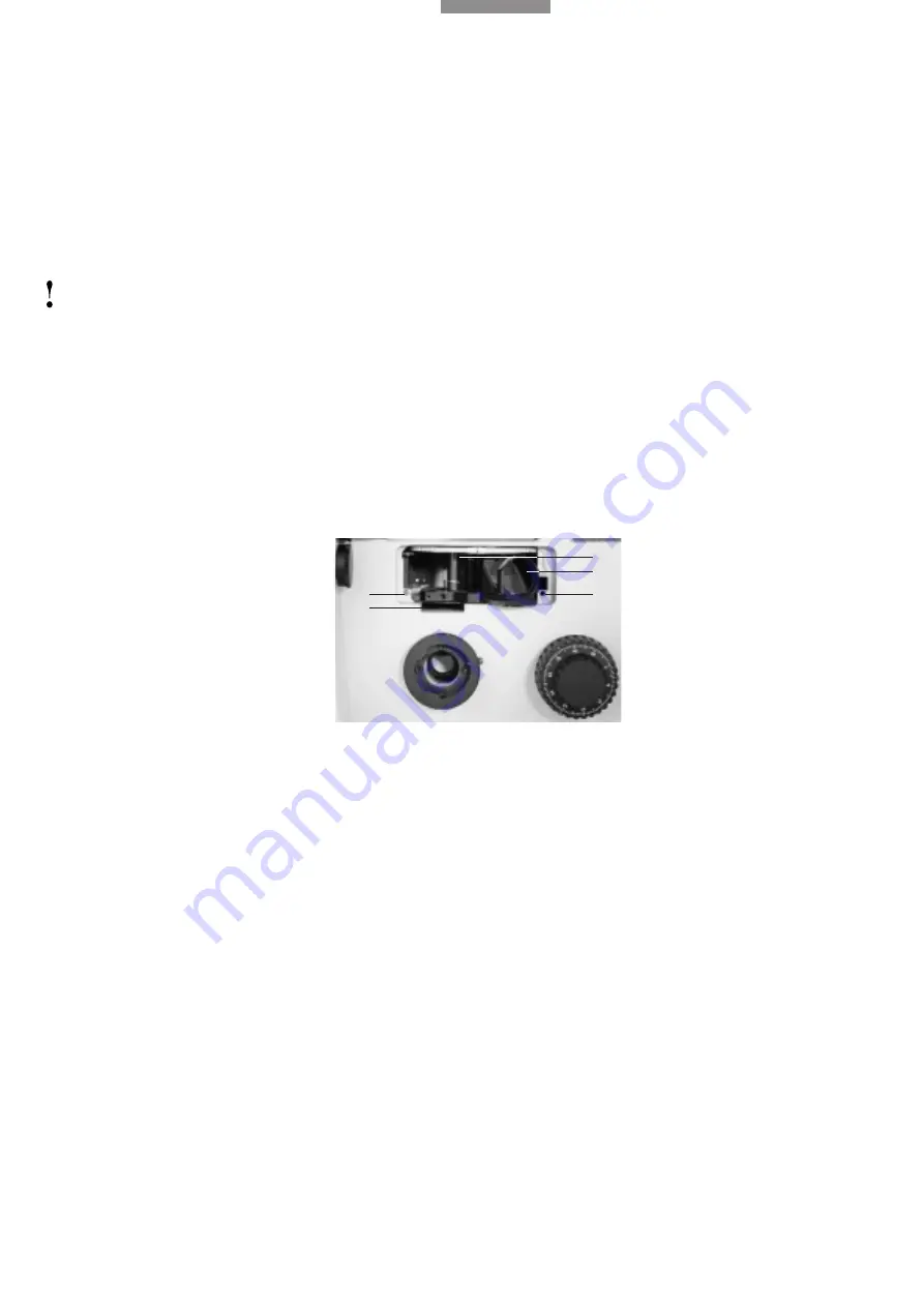
3.7 Inserting the reflectors and fluorescence
filter systems*
Remove the front cover after slackening the Allen
screws.
Insert the reflectors into the dovetail mount as far
as the stop, with the flattened end of the reflector
first and the engraving underneath.
Up to 3 reflector positions can be used by rotating
the turret plate.
n.b.:
Do not touch the optic components of the reflec-
tors!
Before screwing the front cover back on, rotate
the turret plate carefully to check the smooth
rotation of the reflectors.
BF reflector (29)
With neutral plane glass beamsplitter for bright-
field, polarisation contrast and interference con-
trast
Neutral density filter N16 for BF reflector (29.2)
(option)
The neutral density filter N16 can be inserted in
the ring mount of the BF reflector, holding the fil-
ter by the protruding mount.
The neutral density filter is used to avoid damage
to the eyes caused by high light intensity when
changing between bright- and darkfield.
It is not to be recommended for observing dark
objects or for polarisation or interference con-
trast.
Nor is it necessary for purely brightfield configu-
rations without darkfield.
Other reflectors:
DF reflector (30)*
Mirror with centre stop for darkfield observation
only
Smith reflector (31)*
With neutral plane glass beamsplitter 22.5° and
full mirror 22.5° plus compensator lens for bright-
field, quantitative polarisation and interference
contrast.
ICR reflector (32)*
with permanently assembled crossed polarisers
and MgF2 plate for fast switching to interference
contrast without using the polariser/analyser slide.
n.b.: Colour interference contrast is only possible
by adjusting the prisms.
Fluorescence filter systems (filter cubes)
Combination of excitation filter, dichromatic
beamsplitter and suppression filter for wave-
length-specific excitation and imaging of fluores-
cing materials or dyes.
Fig. 28
Inserting the reflectors
1
Screw holes for front cover,
2
Reflector turret,
3
Reflector BF
inserted in dovetail mount,
4
Analyser slot
1
1
4
3
2


