27
3.8 Inserting the ICR prism disc and the ICR
objective prisms
The ICR prism disc with the ICR prisms you or-
dered are already assembled in the microscope
at the factory.
In case you want to retrofit the ICR prism disc,
please proceed as follows:
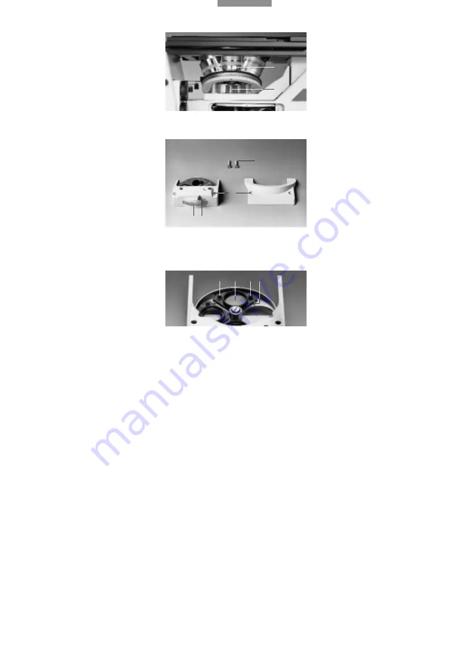
Remove the front cover under the objective
nosepiece (34.2) after slackening the Allen
screws.
Insert the ICR prism disc (34.1) in the mount and
tighten with the two screws. n.b.: insert the prism
disc with the prism mount pointing downwards.
Retrofitting individual ICR prisms:
Please align prisms against the stop pin (35.4)
and only screw down lightly to avoid strain. Insert
the prisms so that the code letter, e.g. A. points
upwards and is readable.
Label the position of the prism on the outside of
the ICR prism disc with label plates (34.5 )
Prism A – for objectives N PLAN 5 x, 10 x
Prisms D and D1 – both for objectives N PLAN
20 x, 50 x, 100 x and HC PL FLUOTAR 5 x–100 x
Differences between prism D and D1
Prism D is the standard prism with greater shear-
ing and therefore higher detection sensitivity for
minute topological and refractive index varia-
tions in the specimen.
Prism D1 has smaller shearing than prism D and
a lower detection sensitivity for topological and
refractive index variations.
However, prism D1 is better at resolving details of
fine specimen structures.
Fig. 33
Assembly of ICR prism disc
1
Objective nosepiece,
2
Mount for ICR prism disc
Fig. 34
Assembly of ICR prism disc
1
ICR prism disc,
2
Front cover under objective nosepiece,
3
Fixing screws,
4
Hole for fixing screws,
5
Label plates,
6
Knurled knob for contrast setting
Fig. 35
ICR prism disc
1
ICR objective prism in mount,
2
Code letter (e.g. A),
3
Fixing
screw,
4
Stop pin
1
2
4
2
3
3
4
5
1
6
2
1


