28
3.9 Inserting the incident light polarisers and
analysers
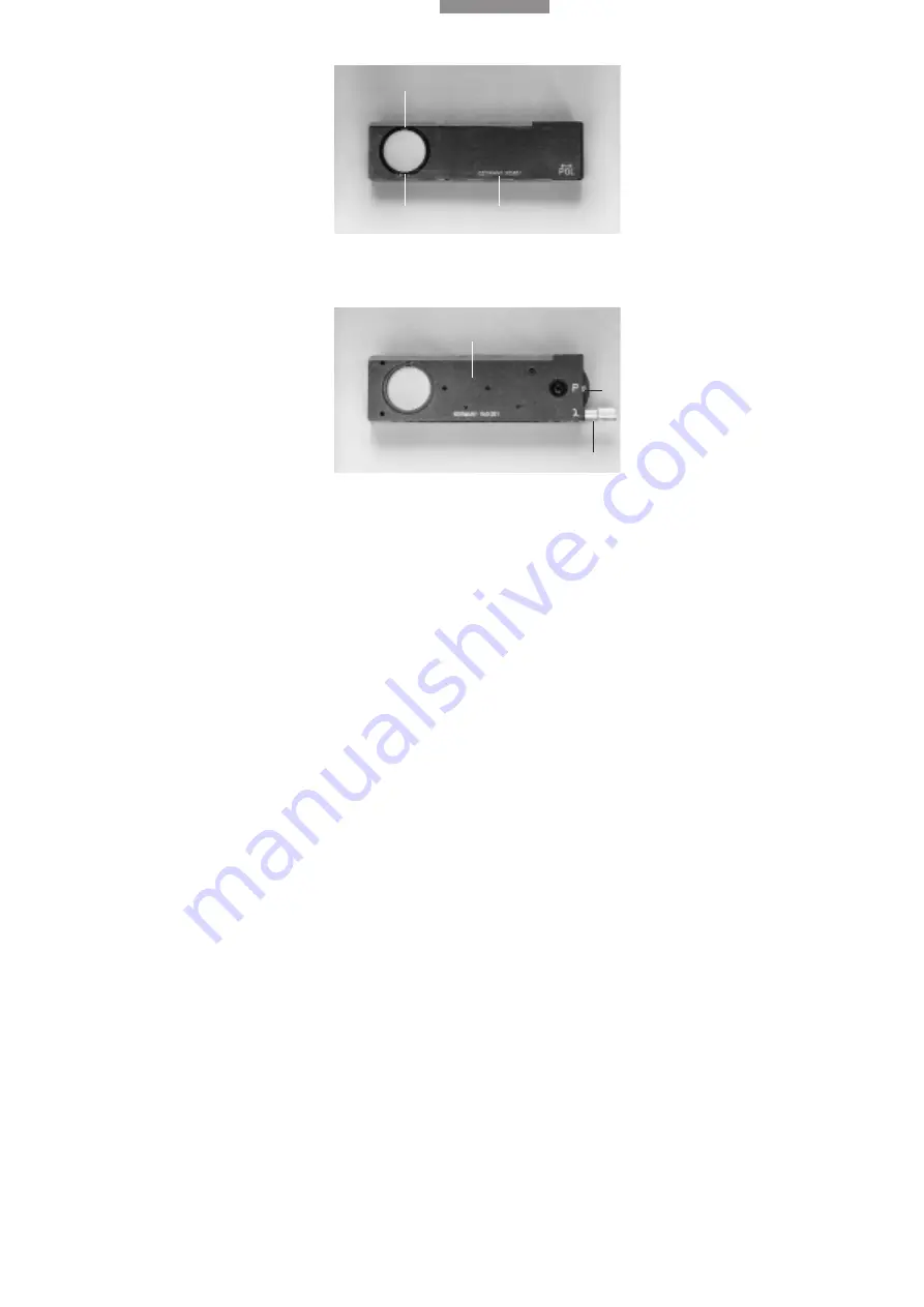
Incident light polariser R/P in slide (36)
Vibration direction of polariser is variable by slot-
ting the polariser at different positions:
0° = east-west
45° = diagonal position
90° = north-south
The DMIRM uses the vibration position 0° = east-
west.
Pull the polariser mount (36.1) out of the slide and
slot it at the corresponding clickstop position.
Together with the IRM ICR/P analyser with 90° =
north-south, the polarisation device is in the
crossed position.
Other incident light polarisers in slide:
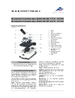
Incident light polariser, 90° rotatable with rota-
table whole-wave compensator (37)
The 0° = east-west vibration direction is intended
for use on the DM IRM.
Preselect the vibration direction 0° = east-west
on the dial (37.2).
Together with analyser IRM ICR/P 90° = north-
south, the polariser and analyser are in the
crossed position.
Polarisation-optic colour contrast is produced
with crossed polarisers and by rotating the
whole-wave compensator with the knurled knob
(37.3).
The whole-wave compensator has a rotation
range of 14° and is particularly advantageous for
variable colour contrasting of anisotropic metal
surfaces.
Fig. 36
Incident light polariser R/P in slide
1
Polariser mount, can be pulled out,
2
Polariser slide,
3
Click-
stop positions 0°, 45°, 90° on back
Fig. 37
Incident light polariser, 90° rotatable with rotatable
whole-wave compensator
1
Polariser slide,
2
Dial for setting polariser,
3
Knurled button
for rotating the whole-wave compensator
1
1
2
3
3
2


