30
3.10 Assembly of the transmitted light illumina-
tion column and the condensers*
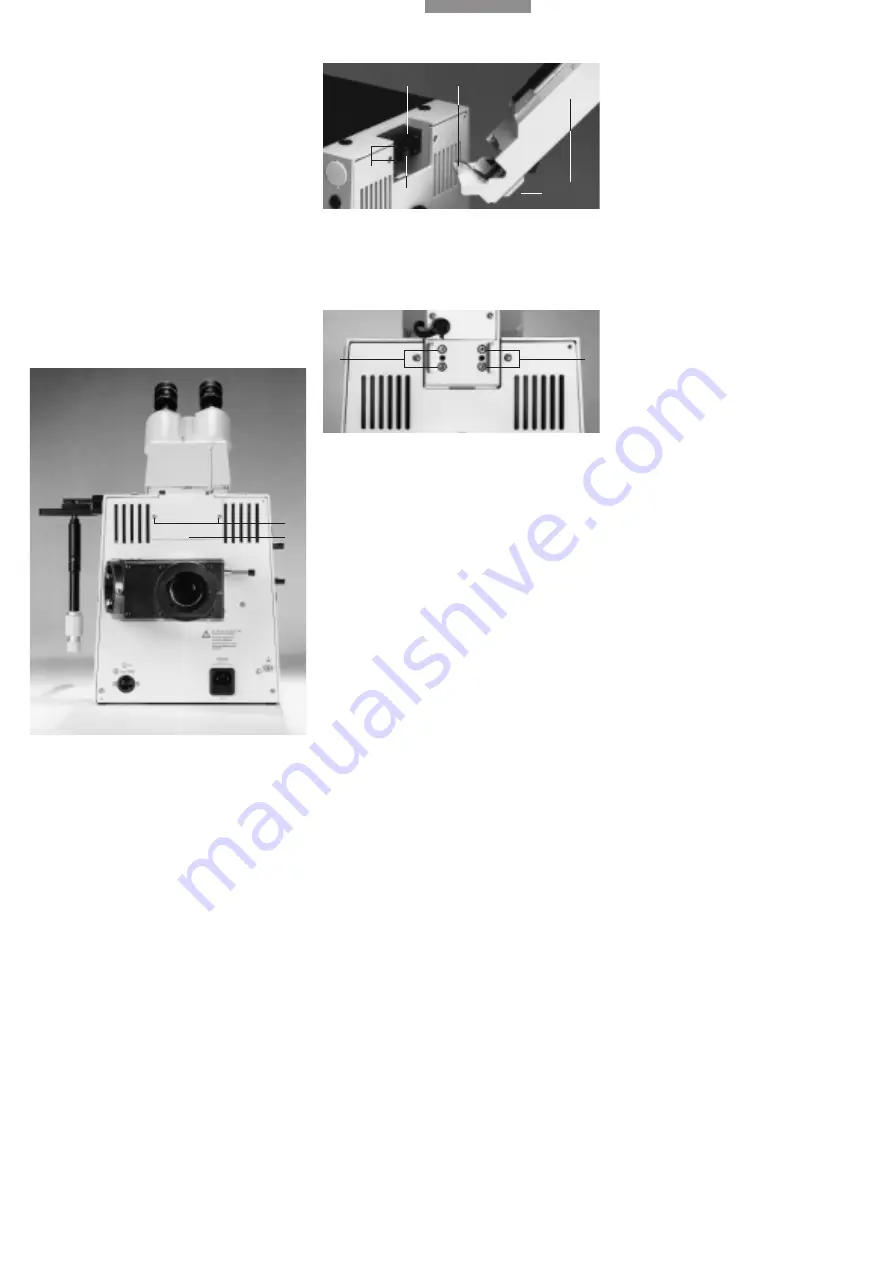
Slacken the 2 recessed head screws (41.2).
Remove the cover (41.1) from the back of the
stand.
Wipe the mount surface (42.3) with a dry cloth.
Tilt the transmitted light illumination column (42.1)
slightly to the back and insert it so that the stud
(42.2) engages in the groove of the mount surface
(42.4). Erect the TL illumination column and fix in
position with the 4 screws (43.1)
Do not hold on to the TL illumination column when
screwing it down, so that optimal alignment to
the optical axis is guaranteed.
Fig. 41
Back view of microscope
1
Cover,
2
Recessed head screws
Fig. 42
Assembly of transmitted light illumination column
1
Transmitted light illumination column,
2
Stud of TL illumination
column,
3
Mounting surface,
4
Groove of mounting surface,
5
Holes for fixing screws,
6
Knurled screw for clamping the illu-
mination column (not assembled)
Fig. 43
Back view of microscope
1
Fixing screws for transmitted light illumination column
1
2
3
4
5
1
1
2
1
6
➝


