background image

102

8. Operation

 8.11  Magnifi cation Changer

Leica DMI3000 B:
A mechanical magnifi cation changer can be 
used optionally. 
Magnifi cation factor: 1.6x.

A slider switches between 1x and the magnifi ca-
tion factor. The mechanical magnifi cation chang-
er affects the eyepieces and the top port.

Leica DMI4000 B and Leica DMI6000 B:
A mechanical magnifi cation changer can be 
used optionally. The following magnifi cation fac-
tors are available: 1.5x, 1.6x and 2x

A slider switches between 1x and the magnifi ca-
tion factor.
The mechanical magnifi cation changer affects 
the eyepieces and the top port.
The selected factor is shown in the LeicaDisplay 
or the relevant window of the Leica Application 
Suite (LAS) and taken into account when calcu-
lating the total magnifi cation.

Leica DMI4000 B and Leica DMI6000 B:
A motorized magnifi cation changer can be used 
optionally. The following magnifi cation factors 
may be selected: 1.5x, 1.6x, or 2x

The selected factor is displayed on the LeicaS-
creen and in the relevant fi eld of the Leica Ap-
plication Suite (LAS), and is taken into account 
when calculating the total magnifi cation. 
The motorized magnifi cation changer affects all 
ports.

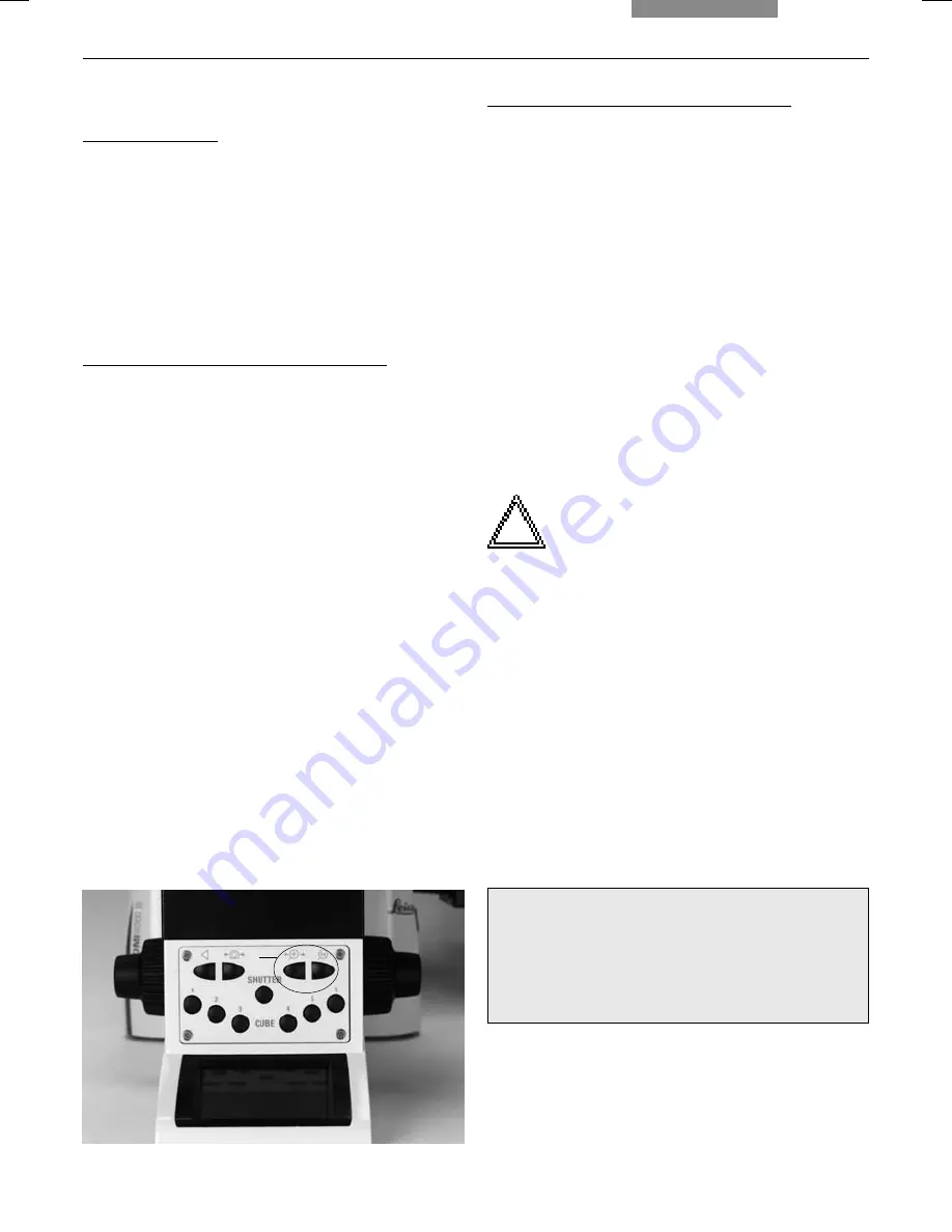
Pressing the left button (117.1) switches between 
the possible magnifi cation factors; pressing the 
right button selects the factor 1x.

   Note:

a microscope can not have both types (manual 
and motorized) of magnifi cation changers.

Fig. 117


 Front control panel

1

  Function buttons for magnifi cation changer

1

1


Change magnifi cation via

fi xed function buttons on stand

Leica Application Suite (LAS) Software

Summary of Contents for DMI3000B

Page 1: ...3 Leica DMI3000B DMI4000B DMI6000B Instructions ...

Page 2: ...7 Checking Phase Contrast Rings 74 7 8 Checking modulation contrast slit diaphragms 77 7 9 Setting the Motorized Polarizer 77 7 10 Adjusting the Light Sources 78 Contents 1 Important Notes about this Manual 7 2 Intended Purpose of the Microscope 8 3 Safety Notes 9 3 1 General Safety Notes 9 3 2 Electrical Safety 10 3 3 Safety Instructions for Handling the Light Sources 12 3 4 Notes on handling las...

Page 3: ... 8 4 Combination Methods 93 8 5 Focusing 94 8 6 Tubes 96 8 7 Port selection 96 8 8 Eyepieces 97 8 9 Objectives 98 8 10 Stages and Object Displacement 101 8 11 Magnification Changer 102 8 12 Light sources 103 8 13 Aperture and Field Diaphragm 104 9 Troubleshooting 105 10 Care of the Microscope 109 10 1 Dust Cover 109 10 2 Cleaning 109 10 3 Handling Acids and Bases 110 11 Major Consumable and Replac...

Page 4: ...9 Aperture diaphragm 10 Focus wheel motorized Leica DMI6000 B manual fine and coarse Leica DMI4000 B 11 Variable function buttons 12 Left side port 13 Booster lens Leica DMI6000 B fluorescence microscopes only 14 Lamp mount fluorescence microscopes only 15 Condenser head 16 Condenser base 17 Field diaphragm 18 Transmitted light lamp housing 19 DIC objective prism disk 1 2 3 4 5 6 7 8 9 10 11 12 13...

Page 5: ...e function buttons 4 Opener for drawer fluorescence microscopes only 5 Drawer fluorescence microscopes only 6 Right side port 7 Analyzer slot 8 Centering window fluorescence microscopes only 9 Field diaphragm centering fluorescence microscopes only 10 Incident light lamp housing fluorescence microscopes only 11 Objective turret 12 Stage with attachable mechanical stage 1 2 3 4 5 6 7 8 12 9 10 11 ...

Page 6: ...iew of the Instruments Fig 3 Front view Leica DMI4000 B and Leica DMI6000 B 1 LeicaScreen 2 Front control panel 3 Port switching 4 Top port 5 Manual transmitted light filters 6 Bertrand lens centering 1 2 3 4 6 5 ...

Page 7: ...te control module Fig 3b SmartMove remote control module 1 Travel in x 2 Travel in y 3 Focus 4 Variable function buttons pre assigned at factory 1 2 3 4 Fig 3a Front control panel 1 Fluorescence cube 2 Shutter 3 100 light to all eyepieces 4 Port selection 5 Magnification selection 6 1x tube lens 1 1 2 5 4 3 ...

Page 8: ...ual adjustments overwrite the previous settings The current setting is stored and is retained from one session to the next when power is switched off 2 Controls SmartMove knobs for stage and focus control Fixed function buttons on stand for INT AP and FD as well as for switching between transmitted light and incident light axis Variable function buttons on stand SmartMove STP6000 These function bu...

Page 9: ...ight incident light axis Change to objective Teach in parfocality Change operating mode dry imm Illumination Manager Magnification changer motorized Focusing 1 Set stops Go to stop Change step increment coarse fine XY stage positioning Change speed Stage positions store go to Change to filter reflector cube Side and bottom port DMI6000 B only DIC fine adjustment Adapted Focus Control AFC always po...

Page 10: ...ube in position 1 6 CHANGE CUBE CW Change cube clockwise 1 4 CHANGE CUBE CCW Change cube counterclockwise 4 1 INT FLUO Increase intensity fluorescence INT FLUO Reduce intensity fluorescence FD FLUO Open field diaphragm fluorescence FD FLUO Close field diaphragm fluorescence CHG FW Toggle filter functions IFW Activate external filter wheel ExMan Activate Excitation Manager SHUTTER FL Open close flu...

Page 11: ...self with the microscope s controls Fig 81 LeicaScreen Initialization 7 2 Switching on the Microscope Leica DMI3000 B Switch on the microscope s power at the On Off switch The signal lamp is lit when the in strument is ready For the Leica DMI3000 B please continue at 7 4 Function Buttons on the Stand Leica DMI4000 B and Leica DMI6000 B Switch on the power of the electronics box at the On Off switc...

Page 12: ...ne 2 objective magnification Line 3 illumination diaphragms Line 4 active ports Line 5 focus stops DMI 6000 B only The content of the display changes according to the active function Contrast method Objective Magnification Focus stops DMI6000 B only Ports Eyepiece Illumination Diaphragm Fig 83 Arrangement of the function buttons overview 1 Four variable function buttons 2 Illumination Manager 3 Fr...

Page 13: ...the Leica DMI3000 B please continue at 7 6 Illumination Leica DMI4000 B and Leica DMI6000 B A number of function buttons are located on both sides of the stand These can be broken down into fixed and variable buttons The variable func tion buttons have different functions depending on the features of the individual microscope Fixed function Buttons on the Left Side The TL IL button 84 1 toggles be...

Page 14: ... Open close aperture diaphragm 3 TL IL switching 4 Open close field diaphragm 5 Increase decrease light intensity Fig 86 Function buttons right side of stand 1 Variable function buttons BF PH ICT DF IMC POL CHANGE TL INT INT AP AP FD FD SHUTTER TL TL FLT 1 TL FLT 2 FLUO CUBE 1 CUBE 2 CUBE 3 CUBE 4 CUBE 5 CUBE 6 AFC ON OFF AFC HOLD CHANGE CUBE CW CHANGE CUBE CCW INT FLUO INT FLUO FD FLUO FD FLUO CH...

Page 15: ... Front control panel 1 100 light to eyepiece 2 Toggle ports 3 Shutter 4 Switch between subsequent magnifications 5 Subsequent magnification 1x 6 Selecting filter cubes Fig 88 1 Focus control buttons 2 Open filter drawer CUBE The CUBE 1 to CUBE 6 87 6 buttons permit the direct selection of indi vidual filter cubes provided the se lected cube is valid for the selected method Press the CUBE 3 and CUB...

Page 16: ...n by turning 89 4 Variable function buttons on SmartMove The variable function buttons are assigned func tions at the factory that are appropriate to the features of your microscope They are labeled accordingly For details on button assignments please refer to the included identification sheet For information on the abbreviations used please refer to the list p 63 Note The Leica Application Suite ...

Page 17: ...via the manual condenser the manual objective turret as well as turning knobs and sliders at the microscope 8 2 1 Bright Field TL Leica DMI3000 B If necessary adjust the TL bright field position at the filter slider Set the condenser to the bright field position Remove all other optical components such as analyzers polarizers or IC prisms from the beam path Insert a transmitted light specimen Sele...

Page 18: ...be switched manually The fluorescence filter turret will automatically go to an empty position or to the A TL filter cube Fig 108 Function buttons left side of stand 1 variable function buttons 2 Open close aperture diaphragm 3 TL IL switching 4 Open close field diaphragm 5 Increase decrease light intensity Fig 109 Function buttons right side of stand 1 variable function buttons 5 4 3 2 1 1 Insert...

Page 19: ...button to switch to transmitted light TL Select the PH phase contrast contrast meth od by pressing the variable button PH Alternatively press the variable button CHANGE TL For details on button assignments please see the identification sheet PH will appear on the LeicaScreen Motorized condensers will now switch to the correct light ring Coded condensers must be switched manually Insert a transmitt...

Page 20: ...Leica DMI6000 B Use the TL IL function button to switch to fluo rescence FLUO Place a specimen on the stage and select a suitable objective The current fluorescence filter cube will be displayed on the LeicaScreen You may protect your specimen from fading by closing the incident light shutter To do so press the SHUTTER button 87 3 on the front panel The following pictogram will appear on th Lei ca...

Page 21: ...eceptacle with the marking facing the user If a homogeneous distribution over the entire field of view is required turn the booster lens 180 so that the marking is facing forward For multiple fluorescence we recommend us ing the Excitation Manager and or the ultrafast internal filter wheel Excitation wavelengths can thus be changed in milliseconds They are controlled by the function buttons Fig 11...

Page 22: ...the display changes accord ingly Place a specimen on the stage and select a suitable objective Select the desired filter cube using the fixed function buttons on the front panel The illumination settings for the fluorescence and transmitted light axes can be adjusted separately Toggle the illumination axes with the TL IL function button The content of the LeicaS creen changes accordingly FLUO DIC ...

Page 23: ...r to the stage initialization when switching the micro scope on The focus buttons Z and Z on the right side of the stand Fig 114 permit fast focusing or lower ing of the objectives Setting stops Set the lower focus stop by pressing and hold ing the SET button and pressing the Z button as well The display will show Pressing the button combination again will delete the stop The display will show The...

Page 24: ...e values have been predefined The assignments can be changed with the Leica Application Suite LAS When selecting Coarse the positioning speed is the same for all objectives Coarse corresponds to the maximum speed Note The assignment of a specific step increment to an objective not only applies to the Z drive but also to the step increments assigned to the stage when Precise p 101 is selected Switc...

Page 25: ... Close any unused tube openings as otherwise stray light can interfere with observation Adjusting the viewing distance Adjust the viewing distance of the eyepiec es so that a congruent total image is seen Fig 115 Adjusting the viewing angle Ergotubes feature a tilting binocular section for a 30 45 viewing angle adjustment range Beam splitting in photo tubes The beam splitting is set manually by pu...

Page 26: ...must be re moved or folded back during microscopy while wearing eyeglasses We recommend removing bifocals and spectacles with progressive addi tion lenses when using the microscope For the adjustable tubes with documentation output choose the 100 VIS position Eyepieces with inlaid reticle Focus the reticle by adjusting the eyelens Focus on the object through this eyepiece Then close that eye and f...

Page 27: ...ositions of the objectives in the objective turret have been specified at the factory and must be observed when installing the objectives also see Objectives p 43 When selecting an objective the microscope au tomatically selects the optimal setting for the field diaphragm the optimal setting for the aperture diaphragm the light intensity for the current contrast method The objective magnification ...

Page 28: ...cated by a color ring in accordance with DIN ISO stand ards Immersion objectives are marked by an addition al lower color ring black oil or Imm universal objective for oil water or glycerin white water orange glycerin The various engraved markings of the objectives provide information on their applications black or bright field objectives dark blue strain free green phase contrast objectives strai...

Page 29: ...from a dry to an immersion objective It also permits the re moval of the liquid when changing to dry mode The current objective remains in the beam path Next press the but on for the objective you in tend to use Note If the Imm or Dry operating mode buttons are pressed accidentally the original mode can be restored by pressing the appropriate button Change operating mode via variable function butt...

Page 30: ... the current ob jective Switch between Precise and Fast via variable function buttons on stand and SmartMove Leica Application Suite LAS Software Fig 116 SmartMove remote control module 1 travel in x 2 Travel in y 3 Focus 4 Individual adjustment of button height 5 Variable function buttons factory preset 1 3 4 5 2 Storing and restoring stage positions A variety of stage positions can be stored tem...

Page 31: ...ation Suite LAS and taken into account when calcu lating the total magnification Leica DMI4000 B and Leica DMI6000 B A motorized magnification changer can be used optionally The following magnification factors may be selected 1 5x 1 6x or 2x The selected factor is displayed on the LeicaS creen and in the relevant field of the Leica Ap plication Suite LAS and is taken into account when calculating ...

Page 32: ...nce Intensity Manager If you continue turning to the left at 100 or to the right after 10 a 0 position shutter posi tion is set Leica DMI4000 B and Leica DMI6000 B Adjust the intensity with the function buttons 118 4 The INT function buttons are always assigned to the currently active transmitted light TL or incident light IL axis For TL and IL The setting can be made in coarse and fine steps Pres...

Page 33: ...t the factory The aperture diaphragm is controlled manually when using the manual condenser The field diaphragm is controlled manually when using the manual illumination arm The motorized diaphragms can be adjusted at any time with the AP aperture diaphragm 118 1 and FD field diaphragm 118 3 function buttons The values displayed on the Lei caScreen change accordingly The function buttons are assig...

Page 34: ...ions Inform Service and have the supply unit fuse checked Open the shutter p 68 Check the connections of the lamp housings on the microscope transmitted light fluores cence Ensure that the lamps are connected to the power supply and are not defective Inform Service and have the ebq 100 supply unit fuse checked Remove all unneeded filters from the light path Center the lamp p 78ff Replace the old l...

Page 35: ...nd that it suits the indication on the objective Ensure that you are using an objective with coverslip correction Adjust the correction ring on the objective if present Be sure that a DF objective is being used The objective aperture is too high maximum 0 7 for condenser S1 maximum 0 4 for condenser S23 28 If necessary reduce the objective aperture us ing the iris diaphragm on the objective Check ...

Page 36: ...they reach maximum darkness without specimen p 87 The specimen is too thick or too thin Embedding medium or specimen are of bire fringent material Rotate the specimen The difference in the refractive indices of the specimen and the embedding medium is too small The cover glass is too thick Check the Koehler illumination p 70 Bring the polarizer and analyzer into cross position until they reach max...

Page 37: ...8 Select the incident light axis IL p 66 Check your specimen e g its antibody binding Insert a new lamp p 45 p 49ff Insert the booster p 92 Center the lamp p 78ff Insert a new lamp p 45 p 49ff Check the cable connections Check whether the cover of the filter disk has clicked into position Check the installed objectives filter cubes etc Switch the microscope off and back on ...

Page 38: ... Ports Eyepiece Focus Lower focus stop not set Lower focus stop set Focus position not set Focus position set Shutter open Shutter closed Transmitted light filter Field diaphragm rectangular Field diaphragm round Aperture diaphragm Light distribution 13 Abbreviations and Pictograms ...

Page 39: ...C Differential Interference Contrast FD Field diaphragm FLUO Fluorescence axis incident light ICR Interference contrast incident light ICT Interference contrast transmitted light IL Incident light INT Intensity IMC Integrated modulation contrast IPH Integrated phase contrast PH Phase contrast POL Polarization incident transmitted light TL Transmitted light ...

Page 40: ...erface 58 Disposal 13 Drawer 21 24 DRY 100 E focus control buttons 21 ebq 100 supply unit 59 81 Electromagnetic compatibility 8 Electronics box 58 64 81 EU directive 8 EXT1 EXT4 sockets 30 Eyebase 96 Eyepiece tubes 20 24 Eyepieces 20 24 43 Fast 101 Field diaphragm 20 66 73 84 104 Field diaphragm adjustment 73 Field diaphragm centering 21 22 26 Filter 44 Filter block 53 Filter cube 52 68 Filter dra...

Page 41: ...hillips screwdriver 30 Pictograms 113 Polarization 107 Polarization TL 87 Polarizer 55 75 Polarizer holder 55 Pollution degree 10 Port 96 Port selection 96 Port switching 22 26 Power input 10 Power supply 59 Precise 101 Protective gloves 48 Protective mask 48 Reflector cube 78 Relative humidity 10 Removing Immersion Oil 110 Replacement eyecup 111 Replacement lamp 111 Replacement of incident light ...

Reviews: