13
4. Description of the LEICA EM KMR2
The scoring and breaking mechanism for knife making are assembled on a heavy,
vibration-absorbing base.
The parts are shown in Fig.9:
1. Clamping lever:
is used to lower and raise the scoring head and also to clamp the
scoring head to the clamping head (No.2). For user-preferred positioning the lever can
be adjusted by pulling it horizontally to the left, rotating it and pushing it back.
The best position is horizontal when clamped with glass in place.This way the same
scoring pressure can always be applied during the knife breaking process.
2. Clamping head:
carries the scoring head and the clamping lever.
3. Scoring head:
carries all necessary elements for scoring and breaking the glass.
The scoring head is lowered into position by means of the clamping lever (No.1).
4. Breaking lever:
is used to break the glass after scoring. By turning the lever slowly
clockwise a pin moves against the glass to break it. This lever can be positioned by the
user by pulling it vertically upwards, rotating it and pushing it back.
5. Ruler:
acts generally as a stop for the glass strip. The glass strip is pressed against the
ruler before it is clamped. The left hand ruler acts also as a track for the moveable stop with
its four click stop positions.
6. Scoring mark selector:
can be set by rotating to two different scoring lengths.
The long score (22 mm) is for scoring the glass strips to break squares for making routine
knives for resin sectioning.
The short score (12 mm) is used to score squares for making high quality knives for cryo
sectioning.
When the long score is used for making knives the quality of the knife is high and also
more reproduceable.
7. Scoring shaft:
is pulled out with reasonable speed to the endstop to score the glass
before breaking.
8. Moveable stop
with its four cklick positions is mounted on the left hand ruler and is
used to break the 400 mm long glass strips according the balanced break method.
9. Rotatable knob:
is used to move the rear stop (No.11) forwards to locate the glass
strips and squares against the ruler.
10. Front stop:
is to hold and position squares during scoring and breaking of knives.
11. Rear stop:
is used to hold and position the glass strips and the squares against the
front stop (No.10) when breaking knives from the square.
Summary of Contents for EM KMR2
Page 2: ...2 ...
Page 4: ...4 ...
Page 8: ...8 Fig 4 Scoring angle Real knife angle Fig 5 Stress line ...
Page 10: ...10 Fig 6 Fig 7 Fig 8 Side view Fig 8 ...
Page 12: ...12 Fig 9 1 2 3 4 5 6 7 8 9 10 11 ...
Page 14: ...14 Fig 10 Moveable stop at position 1 Fig 11 Fig 11a ...
Page 16: ...16 Fig 12 Fig 13 Fig 14 Fig 15 Fig 16 Fig 17 Moveable stop at position 2 ...
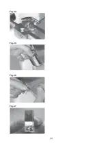
Page 20: ...20 Fig 24 Fig 25 Fig 26 Fig 27 ...
Page 22: ...22 Fig 28 Fig 29 Fig 30 Fig 31 Right hand knife Left hand knife Fig 32 ...
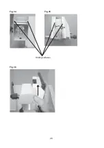
Page 26: ...26 Fig 34 Fig 35 Fig 36 Sliding surfaces ...
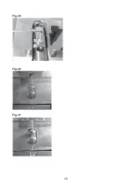
Page 28: ...28 Fig 39 Fig 40 Fig 41 ...
Page 30: ...30 Fig 42 Fig 43 Fig 44 Fig 45 Hotplate Wax bath ...


