


21
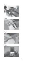
After breaking raise the scoring head completely by means of the clamping lever.
Support head with finger below the scoring shaft to prevent it droping onto the glass.
Push back the scoring shaft and bring the breaking lever to its starting point by rotating
anticlockwise.
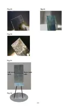
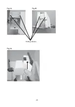
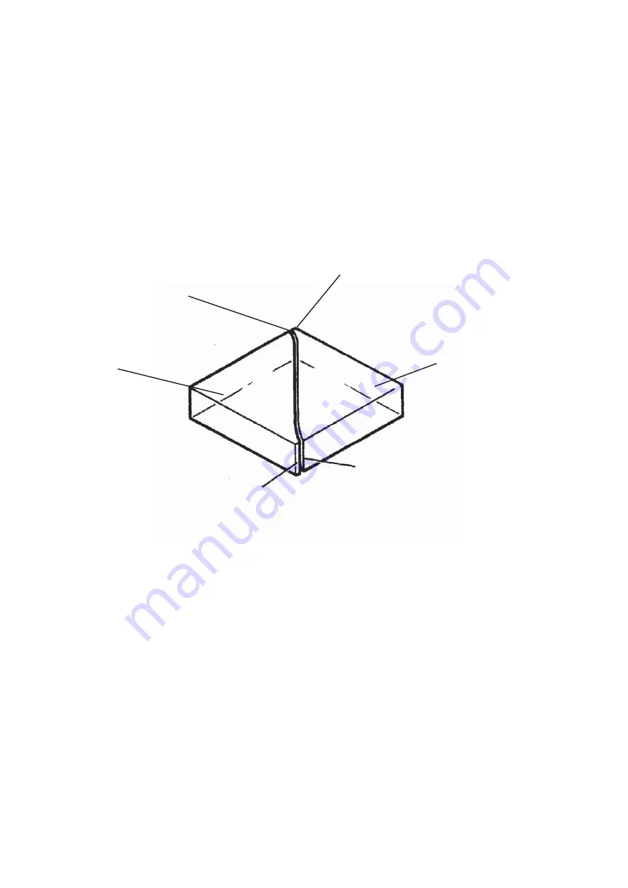
Two knives are now broken from the square
(Fig.24)
.
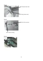
Remove the knives with the hand fork.
We have now produced 2 knives, one on the left and one to the right.
Each of the knives have a knife edge and a knife shoulder
(Fig.24a)
.
Keep the knives together as a ‘pair’.
Take them from the handling fork as shown in
Fig. 25.
Do not allow the knives to touch.
Turn the right hand knife
(Fig.26)
to bring the knife edge side by side with the
knife edge of the left hand knife.
Both knives are know placed together as a ‘pair’ and visual evaluation can be carried out
(Fig.27)
.
Right hand knife.
Left hand knife.
Knife
edge
of the
right
hand
knife
.
Knife
shoulder
of
the
right
hand
knife
.
Knife
shoulder
of
the
left
hand
knife
.
Knife
edge
of the
left
hand
knife
.
Fig.24a
Summary of Contents for EM KMR2
Page 2: ...2 ...
Page 4: ...4 ...
Page 8: ...8 Fig 4 Scoring angle Real knife angle Fig 5 Stress line ...
Page 10: ...10 Fig 6 Fig 7 Fig 8 Side view Fig 8 ...
Page 12: ...12 Fig 9 1 2 3 4 5 6 7 8 9 10 11 ...
Page 14: ...14 Fig 10 Moveable stop at position 1 Fig 11 Fig 11a ...
Page 16: ...16 Fig 12 Fig 13 Fig 14 Fig 15 Fig 16 Fig 17 Moveable stop at position 2 ...
Page 20: ...20 Fig 24 Fig 25 Fig 26 Fig 27 ...
Page 22: ...22 Fig 28 Fig 29 Fig 30 Fig 31 Right hand knife Left hand knife Fig 32 ...
Page 26: ...26 Fig 34 Fig 35 Fig 36 Sliding surfaces ...
Page 28: ...28 Fig 39 Fig 40 Fig 41 ...
Page 30: ...30 Fig 42 Fig 43 Fig 44 Fig 45 Hotplate Wax bath ...


