


9
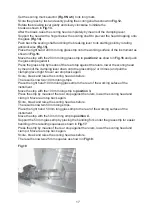
2.3 The real knife angle
When scoring the square all scores stop some distance from the corner.
When pressure is applied under the score, the fracture is initiated and is seen first as a
deepening of the score. The fracture extends towards the corners of the square
following the line of the score. Where the score ends and the break is ”free” the
fracture deviates from the line of the score to curve away from the corner, towards one
of the edges of the square.This results in the real included angle of the knife being
somewhat greater than the angle of scoring.
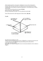
The real angle of the knife increases as the score is moved further from the diagonal.
This is when the knife shoulder becomes larger.
For example, when preparing knives from a square, the real angle of the knife is close to
45° when the knife shoulder is smaller then 0.2mm.
Increasing the height of the knife shoulder (> 0.2mm) results in an even larger
knife angle which can be over 55°
(Fig. 4).
2.4 Length of useful edge
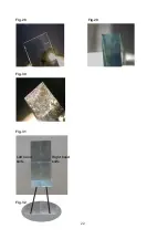
When a glass knife edge is examined under darkfield illumination using a stereo
microscope (or on LEICA Ultramicrotomes using the back light,
chapter 5.4
), it can be
seen that the central part is most useful for ultrathin sectioning. The right side of the edge
has visible marks (saw teeth) which reduce the quality of the knife, and the left corner is
also unsuitable for sectioning because of the stress line
(Fig.5)
.
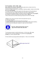
The useful knife edge starts where the stress line does not touch the edge until the part
where the stress marks (saw teeth) can be seen.
Note:
The useful knife edge is 30% longer on knives produced
from 8mm thick glass compared to 6.4mm thick glass!
Note:
When less force has been used to break the knife the
stress line falls away rapidly from the knife edge and fewer
saw teeth can be seen.
Summary of Contents for EM KMR2
Page 2: ...2 ...
Page 4: ...4 ...
Page 8: ...8 Fig 4 Scoring angle Real knife angle Fig 5 Stress line ...
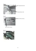
Page 10: ...10 Fig 6 Fig 7 Fig 8 Side view Fig 8 ...
Page 12: ...12 Fig 9 1 2 3 4 5 6 7 8 9 10 11 ...
Page 14: ...14 Fig 10 Moveable stop at position 1 Fig 11 Fig 11a ...
Page 16: ...16 Fig 12 Fig 13 Fig 14 Fig 15 Fig 16 Fig 17 Moveable stop at position 2 ...
Page 20: ...20 Fig 24 Fig 25 Fig 26 Fig 27 ...
Page 22: ...22 Fig 28 Fig 29 Fig 30 Fig 31 Right hand knife Left hand knife Fig 32 ...
Page 26: ...26 Fig 34 Fig 35 Fig 36 Sliding surfaces ...
Page 28: ...28 Fig 39 Fig 40 Fig 41 ...
Page 30: ...30 Fig 42 Fig 43 Fig 44 Fig 45 Hotplate Wax bath ...


