PaveSmart 3D UM
6
How to use this Manual
1
How to use this Manual
Applicability of this
manual
This User Manual is for
, for use to control paving and milling machines.
Introduction to Leica
PaveSmart 3D
Traditionally, paving and milling machines are controlled for elevation and steering by a
stringline. These stringlines are staked-out by a survey crew; positioning the pins and setting
the wires is a demanding and error-prone surveying task. With stringlines in place, they
cause a significant logistical problem for concrete or asphalt delivery and further present a
safety risk for site operatives. Furthermore, damage caused to the stringline, from
personnel or vehicles can seriously interfere with production. Undetected problems with
position or elevation can result in the costly removal and replacement of expensive material.
control system, the machine is controlled without stringlines.
One or two Leica Geosystems robotic total stations (“Robots” - or sometimes referred to as
TPS) or GPS (herein GPS refers to an arrangement including both the United States' GPS and
Russia's GLONASS constellations, and in future the European Union's GALILEO constellation)
sensors continually measure the position of specific points on the machine. These measure-
ments are transmitted by radio to the Leica Machine Computer (MPC1310), mounted on the
machine. High-accuracy machine-mounted slope sensors provide additional information on
the longslope (mainfall) and crossslope (crossfall) of the machine. From this pool of posi-
tion, height and slope information,
then continuously calculates the
current or
Actual
position, elevation and slopes of the machine, and the heading (or direc-
tion of travel) of the machine.
Summary of Contents for MCR-900
Page 1: ...Leica PaveSmart 3D User Manual Version 5 0 English ...
Page 11: ...How to use this Manual PaveSmart 3D UM 11 ...
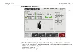
Page 21: ...Getting Started PaveSmart 3D UM 21 Work Screen for Milling Machines a b d c e f g h i ...
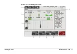
Page 27: ...Getting Started PaveSmart 3D UM 27 Work Screen Mainline Concrete Paver a b c d f g h i j e ...
Page 30: ...PaveSmart 3D UM 30 Getting Started Work Screen Trimmer a b d c e f g h i j ...
Page 99: ...System Components Diagrams Software Description PaveSmart 3D UM 99 ...
Page 107: ...Troubleshooting PaveSmart 3D UM 107 ...
Page 136: ...PaveSmart 3D UM 136 Technical Data Mounting RAM mounting Parameter Data ...


