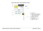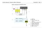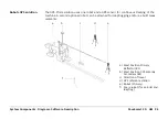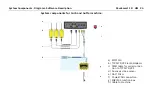
System Components, Diagrams, Software Description
PaveSmart 3D UM
83
3.2
System Wiring Diagrams
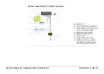
General information
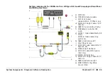
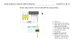
The system wiring is dependent on the purchased/installed solution. The main installation is
identical, only the serial port sensor combination may vary depending on the sensor equip-
ment used. It is possible to attach up to four Robots (when linked to machines using CANBus
interfaces) or up to 2 GPS sensors.
•
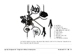
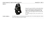
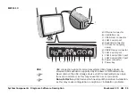
The MPC1310 must be mounted with the bracket supplied. The rear of the MPC1310
should be free from obstructions to allow sufficient cooling.
•
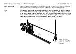
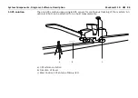
Mast(s) must be fixed firmly to the frame of the machine so minimum vibration is expe-
rienced.
•
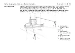
Slope sensors must be mounted at the appropriate point of the machine with the arrow
facing
forward in direction of production.
Use the machine-manufacturer-supplied slope sensor mounting bracket wher-
ever possible.
•
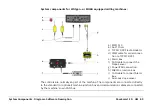
Where applicable: Alternatively to the TCPS27S or TCPS29S ruggedised radio modems,
approved third party radio modems, such as MCR-900, with appropriate cables can be
used. Refer to the Leica PaveSmart 3D Technical Reference Manual for machine-specific
details.
Summary of Contents for MCR-900
Page 1: ...Leica PaveSmart 3D User Manual Version 5 0 English ...
Page 11: ...How to use this Manual PaveSmart 3D UM 11 ...
Page 21: ...Getting Started PaveSmart 3D UM 21 Work Screen for Milling Machines a b d c e f g h i ...
Page 27: ...Getting Started PaveSmart 3D UM 27 Work Screen Mainline Concrete Paver a b c d f g h i j e ...
Page 30: ...PaveSmart 3D UM 30 Getting Started Work Screen Trimmer a b d c e f g h i j ...
Page 99: ...System Components Diagrams Software Description PaveSmart 3D UM 99 ...
Page 107: ...Troubleshooting PaveSmart 3D UM 107 ...
Page 136: ...PaveSmart 3D UM 136 Technical Data Mounting RAM mounting Parameter Data ...

