Getting Started
PaveSmart 3D UM
57
2.8
Positioning the Machine for Production
Get machine onto line
and level
Note the current deviations with as-built checks. Liaise with the machine operator to get
machine approximately onto line and level.
Curb&Gutter, Mainline
and Trimmer
Ensure that the machine controller is set to the correct steering mode (e.g. Leica 3D Mode),
with Steer & Elevation Sensitivities set to Minimum and all control loops set to Automatic.
Start Leica PaveSmart 3D automatic control by pressing the START button for one second.
Milling
Scratch the surface with the drum and dial in the offset you calculated with your as-built
checks. Ensure the controller is showing plausible actual values. Depending on application
and material, go to your milling depth by start manually or directly in Automatic. Check
milling depth immediately with some As-Built Measurements.
Road Paver
Ensure the underlying material to set the screed onto is on the correct height and the tow
arms are in the correct position for the paving depth. Set the screed on blocks to provide
the additional screed height to give the required compaction/roll-down factor (e.g. to
achieve a 100 mm final rolled layer thickness, typically means adding 25% additional mate-
rial, so a 125 mm paving layer thickness is required). Start paving in manual mode and the
check surface height (and make manual corrections using the screed operators' panels).
When the desired height is achieved and the screed has settled into its position and attack
angle, set the corrections (set values) with the actual value and set the machine's levelling
system (e.g. MOBAmatic or Vögele NaviTronic) into Automatic.
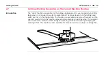
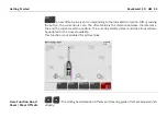
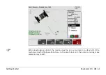
Automatic steering- and screed edge control:
Position the machine within 10 cm (0.3ft) accuracy and
parallel
to the project ReferenceLine.
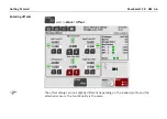
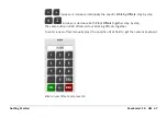
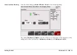
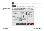
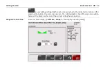
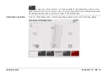
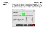
Use the HERE function (
) in the offset dialog to adjust the screed deviations after posi-
tioning the screed edge to its desired width.
Summary of Contents for MCR-900
Page 1: ...Leica PaveSmart 3D User Manual Version 5 0 English ...
Page 11: ...How to use this Manual PaveSmart 3D UM 11 ...
Page 21: ...Getting Started PaveSmart 3D UM 21 Work Screen for Milling Machines a b d c e f g h i ...
Page 27: ...Getting Started PaveSmart 3D UM 27 Work Screen Mainline Concrete Paver a b c d f g h i j e ...
Page 30: ...PaveSmart 3D UM 30 Getting Started Work Screen Trimmer a b d c e f g h i j ...
Page 99: ...System Components Diagrams Software Description PaveSmart 3D UM 99 ...
Page 107: ...Troubleshooting PaveSmart 3D UM 107 ...
Page 136: ...PaveSmart 3D UM 136 Technical Data Mounting RAM mounting Parameter Data ...

