background image

PaveSmart 3D   UM


72

Getting Started

2.12

Backup and Restore

 the Backup button is only active if PaveSmart 3D is in the Config level.

Creating a Backup

PaveSmart 3D Backup contains all projects, all logfiles and all current software settings. It 
can be used to re-establish a certain state on the machine computer for trouble shooting 
purposes. The Backup is also very useful to check the current state for service purposes. For 
example the user can send a Backup to a Leica service engineer to help troubleshoot a 
problem.

NOTE:

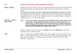
 Leica strongly recommends a Backup be made at the end of each Production shift.

Summary of Contents for MCR-900

Page 1: ...Leica PaveSmart 3D User Manual Version 5 0 English ...

Page 2: ...ase observe the directions and instructions contained in the User Manual and Safety Handbook issued by the Machine manufacturer Controller manufacturer and Sensor manufacturer Product identification The type and serial number of your product are indicated on the label on the base of the product Enter the model and serial number in your manual and always refer to this information when you contact y...

Page 3: ...ers Inc Salisbury NC USA PowerPavers is a registered trademark of PowerPavers Inc Cedar Falls IA USA All other trademarks are the property of their respective owners Type Description Danger Indicates an imminently hazardous situation which if not avoided will result in death or serious injury Warning Indicates a potentially hazardous situation or an unintended use which if not avoided could result...

Page 4: ...42 2 6 Adjusting Working Offsets during Production 49 2 7 Continue Working Depending on the Current Machine Position 50 2 8 Positioning the Machine for Production 57 2 9 Taking As Built Measurements 58 2 10 Leapfrogging Swapping Robots 59 2 11 Checking Instrument Setup Quality and Status 65 2 12 Backup and Restore 72 2 13 Stopping Work End of Daily Production 77 3 System Components Diagrams Softwa...

Page 5: ... Directions 110 6 1 General 110 6 2 Intended Use 110 6 3 Limits of Use 111 6 4 Responsibilities 112 6 5 Software Licence Agreement 113 6 6 Microsoft End User License Agreement EULA 114 6 7 Hazards of Use 125 6 8 Electromagnetic Compatibility EMC 130 6 9 FCC Statement Applicable in U S 132 7 Technical Data 134 ...

Page 6: ...n can result in the costly removal and replacement of expensive material With the Leica PaveSmart 3D control system the machine is controlled without stringlines One or two Leica Geosystems robotic total stations Robots or sometimes referred to as TPS or GPS herein GPS refers to an arrangement including both the United States GPS and Russia s GLONASS constellations and in future the European Union...

Page 7: ...g with the conventional stringline sensors Contents of this manual The Leica PaveSmart 3D User Manual is designed into four main sections System setup Information is presented in a step by step format 1 Getting Started Daily Operations Project Setup Hints and Tips 2 System Components Diagrams Software Description 3 Troubleshooting Detailed Troubleshooting Chart 4 Care and Transport Safety Directio...

Page 8: ...ch are considered as self explanatory are not explained Available documenta tion Name of documentation Description Leica PaveSmart 3D User Manual All instructions required in order to operate the system to a basic level are contained in this User Manual It provides an overview of the system together with technical data and safety directions Leica PaveSmart 3D Tech nical Reference Manual for Curb G...

Page 9: ...o Manual North America only Contains important safety directions as well as technical instructions for setting up the MCR 900 radio modems and operating them optional MPC1310 User Manual Contains important safety directions as well as a general description of technical processes and instructions for using and operating the MPC1310 Leica GNSS Machine Posi tioning User Manual Contains important safe...

Page 10: ...commencing working on the machine Format of the docu mentation The user manuals are available in printed form and can be downloaded on MyWorld NOTE Leica Geosystems strongly advises reading the relevant machine operating safety instructions provided by your machine manufacturer ...

Page 11: ...How to use this Manual PaveSmart 3D UM 11 ...

Page 12: ...to the machine Connect power radio and CAN cables if available Machines using CANBUS communication should be connected by the MJB1305 Paving Junction Box Set up all required sensors Robot and GPS reference station if applicable with the required accessories battery radio and cables Ensure that all robots are running either in MGuide with the appropriate configuration set or correctly configured wh...

Page 13: ...to obtain correction data for the GPS machine sensor refer to the Leica GPS Machine Positioning User Manual At the Leica PaveSmart 3D computer In the dialog Work Sensors Arrange select which sensor will be used as Primary depending on configuration profile and optionally as Secondary and Spare Switch on machine and allow hydraulic system to warm to a suitable operating tempera ture before starting...

Page 14: ...ing the key for 1 second the power indicator LED will show green and the MPC1310 will start booting up Ensure that there is sufficient power supply If not switch on the ignition of machine or start the engine Warning ALWAYS disconnect the Machine PC power and or CAN cable to the machine before conducting hot work welding on the machine Reconnect the cabling only after completion of hot work weldin...

Page 15: ...Smart 3D UM 15 Main Menu Dialog In all dialogs the following buttons are used to navigate confirm or reject changes to settings confirm changes to system settings and continue reject changes and go back to previous dialog ...

Page 16: ...nsors General settings such as units language date time etc To define machine profile machine dimensions control points interval periodic actions locks and stops production tolerances and advanced machine tuning options Diagnostic tools for data flow and the external radio configuration tools Unlock the protected dialogs if disabled opens a dialog to enter the password Contains various tools for e...

Page 17: ...r Trimmer Profiles are avail able depending on the Licences purchased Further licences can be purchased through your Leica Machine Control sales representative The Work dialog screen shows all the information needed while the machine is in operation Field Description SW Version The build number of the software Please quote this number to support CCP Expiry The date of expiry for maintenance contra...

Page 18: ...ard Error messages the specific icon flashes yellow if a warning is detected or flashes red if an error occurs By pressing the specific button additional information and trou bleshooting tips will be displayed 1 MPC1310 messages 2 Communication messages a b d c e f g h i j ...

Page 19: ... d Information provides information about the work progress Stationing shows current Stationing or Chainage in selected units Opposite Stationing shows the inverted Stationing or Chainage the difference to the end in selected units Speed indicates current Speed of the machine in m min or ft min Working Slope shows the current Working Slope which is the Design Slope at the current position plus the...

Page 20: ...steer where applicable control j press and hold for at least 1 second to stop active Control and for at least 2 seconds to close the software and shut down the MPC1310 Never power off the MPC1310 by holding down the Power Key Always shut down the MPC1310 by using the Exit button to ensure that all data and system settings are saved ...

Page 21: ...Getting Started PaveSmart 3D UM 21 Work Screen for Milling Machines a b d c e f g h i ...

Page 22: ... manually on the controller or automati cally through PaveSmart 3D c Design Map display shows the whole project and the current machine position Click on the Map to select the desired Reference Line and Slope Line d Information provides information about the work progress Stationing current Stationing or Chainage in selected units Opposite Stationing shows the inverted Stationing or Chainage i e t...

Page 23: ...t 3D software h press and hold for at least 1 second to stop active Control and at least 2 seconds to close the software and shut down the MPC1310 Never power off the MPC1310 by holding down the Power Key Always shut down the MPC1310 by using the Exit button to ensure that all data are saved ...

Page 24: ...PaveSmart 3D UM 24 Getting Started Work Screen Road Paver in Vögele NaviTronic configuration a b d e c f g h i j ...

Page 25: ...t correction buttons Set Value c Screed Information for Vögele pavers only indicates the corrections for the Screed Edge left and right Inside the box the current total width of the screed and width for left side of the screed 1 250 m and for the right side of the screed 1 260 m d Information provides information about the work progress Stationing shows current Stationing or Chainage in m or ft Sp...

Page 26: ...re i press and hold for more than 1 second to stop active Control and more than 3 seconds to close the system software and shut down the MPC1310 Never power off the MPC1310 by holding down the Power Key Always shut down the MPC1310 by using the Exit button to ensure that all important project data are saved ...

Page 27: ...Getting Started PaveSmart 3D UM 27 Work Screen Mainline Concrete Paver a b c d f g h i j e ...

Page 28: ...rence Line Slope Line and Working Offsets For example if the Left Front height correction shows 0 013 in m or ft the machine has to raise the left front of the mold by 0 013 in m or ft c Information provides information about the work progress like Stationing Chainage Speed Design Slope Next Action and Sensor Information d Design Display shows the whole project and the current machine position Cli...

Page 29: ...uning dialog to set the hydraulics parameters for the machine j press and hold for at least 1 second to stop Active Control and at least 3 seconds to close the software and shut down the MPC1310 Never power off the MPC1310 by holding down the Power Key Always shut down the MPC1310 by using the Exit button to ensure that all data are saved ...

Page 30: ...PaveSmart 3D UM 30 Getting Started Work Screen Trimmer a b d c e f g h i j ...

Page 31: ...tion with the machine s controller set to Automatic the deviations should be around zero at all times c Design Map display shows the whole project and the current machine position Click on the map to select the desired ReferenceLine and SlopeLine for controlling the machine d Information provides information about the work progress Chainage shows current Stationing or Chainage in selected units Sp...

Page 32: ...ensors etc i opens the Tuning dialog to adjust the hydraulics sensitivity for the machine s eleva tion and steer where applicable control j press and hold for at least 1 second to stop active Control and for at least 2 seconds to close the software and shut down the MPC1310 Never power off the MPC1310 by holding down the Power Key Always shut down the MPC1310 by using the Exit button to ensure tha...

Page 33: ...d automatically Edit the current or enter a new value and press OK The keyboard will close and the new value will be used If you have made a mistake simply press again to edit the number key toggles the sign of the number between positive and negative DEL deletes entered values ESC abandons changes and reverts to the initial value ...

Page 34: ...d Text keyboard By pressing in any text edit field the text keypad will be open automatically Enter or edit text and press OK This keyboard operates similarly to the numeric keypad Refer to Numeric keyboard page 33 for more information ...

Page 35: ...r the processing power required to run the system A balance must be found between the number of segments required to define the design and the processing power it will require The recommendations detailed below must be followed when creating designs Without following these rules Leica Geosystems cannot guarantee good quality paving performance Angle change between segments Leica PaveSmart 3D is ca...

Page 36: ...o connected line segments must never be greater than 1 degree 1 When defining a straight line it is not necessary to add more points in the middle of a line Number of Segments The number of segments contained within a single job should ideally not exceed 3500 indi vidual elements It is possible to have multiple stringlines on the same layer but each indi vidual job should ideally not exceed 3500 e...

Page 37: ...Getting Started PaveSmart 3D UM 37 2 4 Preparing the Leica PaveSmart 3D Software for the Current Project Creating a new project start from Menu Projects Current create a new project ...

Page 38: ...arted Entering Name and Comment New Project Name Enter the name of the new project Project names cannot contain special characters and spaces Comment Enter a comment to describe the project in detail confirm the input and continue ...

Page 39: ... folder does not already exist on the stick use Windows Explorer to create the folder Importing jobs from USB Port The USB port labelled USB A is located on the bottom of the MPC1310 Connect your USB storage device with the prepared design data on it to the USB port on the MPC1310 The design data must be stored on the storage device in a folder named DBX a MPC1310 b USB storage device b a ...

Page 40: ...e job type you want to work with StringLine is selected as the default Design Type StringLine Job shows the currently selected StringLine job Only one layer from the stringline job can selected at a time Select the appropriate layer from the Layer dialog confirm the selections and continue ...

Page 41: ...ting the current Project The newly created project is automatically highlighted as the current project If a different project is required it may be selected confirm the selection and continue New Project created but not selected Back to Menu ...

Page 42: ...tting Started 2 5 Selecting Design Reference Lines Design dialog From the Work dialog click on the Design window to see the Work Design dialog set all deviations to zero This function is not available for all machine types ...

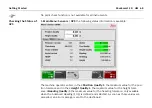
Page 43: ...ning automatically the next reference line on the left and the right side of the machine or its height control point to calculate the design height and slope Manually you chose the ReferenceLine and optional a SlopeLine When using the Road Paver profile this can be disabled in Menu Preferences General Disable Automatic Line Selection When using the screed extension control with the Vögele NaviTron...

Page 44: ...PaveSmart 3D UM 44 Getting Started After choosing a ReferenceLine the procedure prompts the user to choose EdgeLines Choose the EdgeLine for both sides of the screed These are optional ...

Page 45: ...the project use the graphical zoom function to zoom in and out the current design window use the graphical rotation function to rotate the whole design confirm the highlighted ReferenceLine and continue Selecting EdgeLines This feature is only available for the Vögele NaviTronic controller Line colours for RefLine SlopeLine and ScreenEdge The RefLine is shown in green The SlopeLine and the ScreenE...

Page 46: ...veSmart 3D UM 46 Getting Started Entering offsets start in Work Offset The offset dialog can look slightly different depending on the loaded profile and the attached sensors the functionality is the same ...

Page 47: ...ic Working Offsets step by step increase or decrease both Front Offsets together step by step The same button in RED affects all four Working Offsets together To enter a new offset manually press the specific offset field to get the numeric keyboard Enter a new offset and press OK ...

Page 48: ...ter the Front and or Rear Left and or Right elevation offsets Refer to Entering offsets in the beginning of this chapter from Work Elevation Offsets Slope Offset Enter the Cross Slope offset in the same way as the elevation offsets The cross slope offset determines catch spill curb if there is no cross slope information in the job Only available for machines using a cross slope sensor to control t...

Page 49: ...range and atmospheric effects e g temperature cycling during the working period pressure humidity The importance of as built checks see 2 9 Taking As Built Measurements and good survey practice cannot be overstated these will ensure any subtle errors and or external influences do not impact on the accuracy and quality of the paving milling process Adjustments to Working Offsets should only be made...

Page 50: ...quired to work in parallel lanes The lanes depend on the milling head width and not on the design data The function is used when one lane is finished and the operator wants to turn the machine around and work along an existing edge The operator can use the Here function which brings the steering correction to zero by changing the steering offset The function is also available for elevation and cro...

Page 51: ...re Function Steering From the Work dialog go Work Offsets Steer to the following dialog The setting Reference Right sets the offsets to be measured to the right side of the milling head Other options are Reference Center and Reference Left ...

Page 52: ...he offset value is the distance between the reference line and the current machine position The currently selected steer and slope lines will also be updated to the closest available This function is not enabled for all machines Here Function Road Paver Steer Offsets The milling head elevation Offsets and steering guide offset are adjusted indi vidually ...

Page 53: ... 53 enters an Offset that makes the Correction zero machine will mill at this elevation offset All 3 offsets are changed simultaneously in parallel Here Function Eleva tion From the Work dialog go Work Offsets to the following dialog ...

Page 54: ...g to the indicated correction After pressing the button the correction is zero The cutting depth is the difference in elevation between the design surface and the current milling head elevation Slope Here Function From the Work dialog go Offsets Slope to the display following dialog ...

Page 55: ...indicated correction After pressing the button the correction is zero The cross slope offset is the difference between the design slope and the current cross slope of the milling head Overall Here Function From the Work dialog press on the Design Map graphic to get to the following dialog ...

Page 56: ...log all of the above mentioned Here Functions are combined The Here button in the Graphic dialog sets the steering offset the cutting depth and the slope offset simultaneously so that all the corrections are zero This function is not enabled for all machines ...

Page 57: ...ilt Measurements Road Paver Ensure the underlying material to set the screed onto is on the correct height and the tow arms are in the correct position for the paving depth Set the screed on blocks to provide the additional screed height to give the required compaction roll down factor e g to achieve a 100 mm final rolled layer thickness typically means adding 25 additional mate rial so a 125 mm p...

Page 58: ...er or iCON User Manual and the Geo Pad User Manual or Site Foreman User Manual on how to take As built measurements Display and recording As built control meas urements Immediately after an As built control measurement has been made the results can be seen in the Work Design dialog The results are also recorded in the active project folder in the file Asbuilt abr Work Menu Projects AsBuilt and can...

Page 59: ...rial or a truck Setting the leapfrog parameters Work Sensor Arrange Leapfrog tolerance The maximum deviation between the currently measured prism coor dinates and the newly measured prism coordinates must be set Use shortest measuring distance The details of the robot for Position Easting Northing and Elevation Height to be removed from active control process must be selected If the Leapfrog from ...

Page 60: ...nt is switched on correctly positioned orientated then verify the battery condition and cabling and finally that the radio communication settings link number and COM Port are correct Ensure that the instrument uses the appropriate machine guidance application The system automatically takes the desired robot nearest or furthest measuring out of active control and assigns it as the Spare sensor repl...

Page 61: ... PaveSmart 3D UM 61 Before leapfrogging a Robot the machine must be at or very close to a stand still If the machine is moving the Spare Robot may not be able to lock onto the prism and wrong meas urements may result ...

Page 62: ...ed to prevent any steps or lines appearing in the surface This usually occurs before the Spare Robot takes active control of the machine Steps may be introduced due to minor changes errors in the positions orientations of the robots the accuracy of the instrument position orientation is heavily dependent on the quality and location of the local site reference points and measurement distance ...

Page 63: ... small offset changes if absolute position control and paved milled surface smoothness is important Auto Elevation Offset adjustment Work Sensor Leapfrog Auto Elev The Auto Elevation button will only change the elevation offsets by the difference in height between the old measurement and the new measurement at the front and rear of the mold The steering offsets will remain as they were before the ...

Page 64: ...be removed by manually changing the Sensor Arrangement or pressing the RESET button in Main Menu Tools Data Flow Sensors Primary or Secondary For curb and gutter milling and asphalt machines the leap frog corrections are applied by changing the users steering and elevation offsets These corrections can be removed by altering the offset values to their original values ...

Page 65: ...been standing for a long time e g 2 hr at the same setup TPS1200 and Viva instruments Using the Tiepoint Check function from the Work dialog press SENSOR and define the instrument with should be verified Refer to the MGuide User Manual Chapter 5 for further details TPS1200 or Viva can only measure to the predefined point from the fixpoint job see MGuide User Manual page 4 15 The horizontal distanc...

Page 66: ...ith GPS GNSS Receivers Wait for the results to be displayed this will take several seconds as the instrument turns to the required position and measures the prism The instrument will then return to its previous position The result is displayed after the robot measurement to the preselected fixpoint If the result is within the tolerance the Correction is displayed with a green back ground colour ...

Page 67: ...ne predefined tolerance is exceeded the result of the Tiepoint Check is displayed with a red background colour If the tolerance of one result is too large a new setup of the robot is strongly recom mended If no measurement is possible an error message will be displayed Check the communi cation the robot target line and the robot settings ...

Page 68: ... available The machine operator enters in the Position Quality the maximum value for the posi tion tolerance and in the Height Quality the maximum value for the height toler ance Heading Quality the maximum value for the heading tolerance only available when the Advanced Heading 1Up is defined and selected As soon as these values are exceeded an error message is sent to the dashboard ...

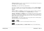
Page 69: ...t the satellite constellation From those values the Pos Quality and the Height Quality are calculated Easting Northing and Height are the coordinates of the current sensor position Depending on the GNSS receiver settings the Local Coordinates might not be displayed For example when using the Advanced Heading 1Up option Refer to PaveSmart3D Technical Reference manuals for more details Heading Quali...

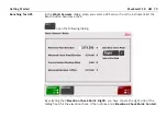
Page 70: ... when you select a GPS sensor from the instrument list the Bench button becomes active open the following dialog By selecting the Elevation Check Point Right you have chosen the right side of the milling head for the elevation check Other options are Elevation Check Point Center ...

Page 71: ...e ments are taken during this time The Measured Check Point Elevation is the current elevation of the milling head meas ured with the GPS sensor The difference between the measurement and the reference point elevation is the Current Sensor Elevation Offset stores the current sensor elevation offset From now on this offset is considered in the calculation until a new offset is determined with the B...

Page 72: ...files and all current software settings It can be used to re establish a certain state on the machine computer for trouble shooting purposes The Backup is also very useful to check the current state for service purposes For example the user can send a Backup to a Leica service engineer to help troubleshoot a problem NOTE Leica strongly recommends a Backup be made at the end of each Production shif...

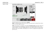
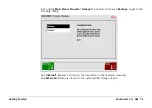
Page 73: ... In the dialog Main Menu Projects Backup the operator chooses Backup to get to the following dialog An Internal Backup is stored on the local drive on the machine computer An External Backup is stored on the external USB storage device ...

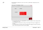
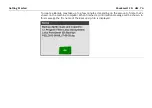
Page 74: ... To create a Backup may take up to a few minutes depending on the amount of data that s stored on the machine computer When finished a confirmation message will be shown In this message the file name of the Backup zip file is displayed ...

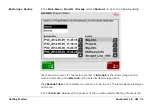
Page 75: ...here are two sources for the restore process Internal is the local storage on the machine computer and External is the external USB storage device The Backup Files of the selected source are shown in a list The latest Backup is always on the top In the Content window all the projects of the currently selected Backup file are listed ...

Page 76: ...76 Getting Started restores the selected Backup and overwrites all projects all logfiles and all current software settings Before the current settings and data are over written an internal Backup is automatically done ...

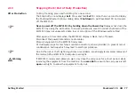
Page 77: ... data loss or corruption of the Windows system files After approx 30 seconds when the MPC1310 display is black turn off power Disconnect the power data cables radio cables Store all equipment in the MPC1310 carrycase Fit dust water caps for machine mounted connectors where provided to prevent rain or condensation build up which may lead to electrical problems Due to the risk of theft lightning str...

Page 78: ...pplied packaging for transport and study the relevant documenta tion for cleaning and maintenance work refer to 5 Care and Transport System hardware The installed components on the machine comprise a Machine Computer with attached radio modem s to communicate with the robot s dual slope sensor mast s with attached reflector or optional GPS antenna As well as the installed components on the machine...

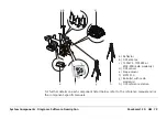
Page 79: ...etails on each component listed below refer to the reference manual and or the component specific manuals a Reflector b GPS antenna c TCPS27S TCPS29S or MCR 900 radio modem s d GPS sensor e Slope sensor f MPC1310 g Robot s with radio modem s h GPS reference station a e b c d f g h ...

Page 80: ...RO for machine automation The MNA1202 GG antenna mounted on the secondary mast of the machine Except North Americas TCPS27S or TCPS29S radio modems with ITT Cannon connectors are used on the machine and communicate with the TPS1200 or Viva Radio Handle mounted on the instrument For further information refer to the TCPS27 29 user manual ...

Page 81: ...ne dual axis slope sensor with a CAN interface is used Mounted at the recommended position on the machine and the arrow must always face the normal forward working direction The MPC1310 is a ruggedised computer with Windows XP Embedded touchscreen milspec connec tors for power CAN four serial RS232 and USB inter faces Bracket to mount Machine Computer for easy installation and removal at the end o...

Page 82: ... manual and or the component specific manuals The system supports TPS1200 and Viva Total Stations with the onboard software application MGuide and it supports the iCON Robot and Leica Captivate Total Stations with the onboard MC application The radio modem is optionally integrated into the handle of the instrument For further information refer to the instruments user manual ...

Page 83: ...cket supplied The rear of the MPC1310 should be free from obstructions to allow sufficient cooling Mast s must be fixed firmly to the frame of the machine so minimum vibration is expe rienced Slope sensors must be mounted at the appropriate point of the machine with the arrow facing forward in direction of production Use the machine manufacturer supplied slope sensor mounting bracket wher ever pos...

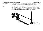
Page 84: ...one prism solution can only be used with one track steer machines such as Gomaco GT3200 series curb gutter offset paver Wirtgen SP15 or PowerCurber 5700 series offset pavers or where the steer function rear track s of an all track steer machine are disabled ensure to verify that track angle is perfectly parallel to the machine travel direction otherwise poor paving quality results a Mast Position ...

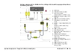
Page 85: ...t Cable 7S 7P CAN 3m e MJB1305 Junction Box Paving f MOBAMatic Controller DLS v4 28 g MCCS17 Coiled Cable Mach All Pins MCCS18 Coiled cable only Up On 3m h MJB15 Junction box left i Mast Slope Sensor j MCC1201 Coiled Cable CAN 7P bayonet 6m k MPR122 360 Reflector l MYC1307 Cable MPC Generic CAN 35cm m MSS24 3D Alarm box n MSC1201 Straight Cable 7S 7P CAN 3m o MJB16 Junction box right p MMs8 MMatic...

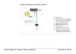
Page 86: ...e a MPC1310 b TCPS27S 29S radio modems c PWM cables for serial connec tion s to TCPS27S 29S d PWM cable for serial connec tion COM3 to TCPS27S 29S e Dual axis slope sensor f 360 Prism g Power CAN connection h MJB1305 Junction box i Cable to machine usually supplied by machine manu facturer as part of 3D Kit a b c e f d g h i ...

Page 87: ...for Trimmer machine a MPC1310 b TCPS27S 29S radio modems c PWM cables for serial connec tion s to TCPS27S 29S d Dual axis slope sensor e MJB1305 Junction box f 360 Prism g Power CAN connection h Cable to machine usually supplied by machine manu facturer as part of 3D Kit a b c e f d g h ...

Page 88: ...cription 1 GPS solution The one GPS solution uses a single GPS sensor for continuous tracking of the machine An optional robot can be attached for as built measurements a GPS reference station b Direction of travel c Mast Position GPS antenna Primary B1 c b a ...

Page 89: ...cted directly to the standard or optional machine junction box and communication cables are connected by the machine s own CAN bus a MPC1310 b 360 Prism c TCPS27S 29S radio modems d PWM cable for serial connec tion to TCPS27S 29S e Alarm box f CAN cable to connect the Slope Sensor g Power CAN connection h MJB1305 Junction box i CAN cable to connect Alarm box j Dual axis slope sensor a b c e f d g ...

Page 90: ...r as built measurements For caterpillar tracked Vögele roadpavers equipped with the latest NaviTronic system this arrangement can also regulate automatic steering direction of the machine Refer to Vögele for details of NaviTronic autosteer compatible machines a Mast position Primary reflector B1 b Robot c Mast position Secondary reflector B2 d Direction of travel e Robot f Spare robot for as built...

Page 91: ... UM 91 System components for Vögele Road Paver machine a MPC1310 b TCPS27S 29S radio modems c PWM cables for serial connec tion s to TCPS27S 29S d Dual axis slope sensor e MJB1305 Junction box f 360 Prism g Power CAN Connection h Cable to machine a b c e f d g h ...

Page 92: ...scription System Components for Mainline Paver a MPC1310 b 360 Prism c TCPS27S TCPS29S radio modems d PWM cables for serial connec tion s to TCPS27S 29S e Dual axis slope sensors f Power CAN connection g MJB1305 Junction box h Cable to machine a b c e f d g h ...

Page 93: ...a GPS sensor for continuous tracking of the machine A second optional robot can be attached for leapfrogging and or as built meas urements a Mast Position Primary Reflector B1 b Mast Position GPS antenna Secondary B2 c Direction of travel d GPS reference station e Robot Primary f Spare robot for as built and leapfrog b c d e a f ...

Page 94: ...cription System components for Curb and Gutter machine a MPC1310 b TCPS27S 29S radio modems c PWM cable for serial connec tion to TCPS27S 29S d Dual axis slope sensor e 360 Prism f Power CAN connection g MJB1305 Junction box h Cable to machine a b c e f d g h ...

Page 95: ...tor l Power key USB USB connection supports Leica Geosystems USB storage device or standard USB keyboards supported by Windows XP Embedded only Never remove the USB storage device until file read write copy opera tions are completed as this may cause file loss or corruption Do not attach any USB device which needs additional driver installation as this may cause configuration corruption or install...

Page 96: ...ected Power key To turn On and Off the Machine Computer Caution Never turn Off the Machine Computer without shutting down all running applications This could result in unexpected data loss Precautions Black screen must be displayed after pressing the Shutdown button in Leica PaveSmart 3D software before switching the power off to the MPC1310 KEYBOARD Permits connection of external keyboards with c...

Page 97: ...on is calculated with attached robot or GPS tracking data and the slope sensor s mounted on the machine The calculated deviations are then according to the control parameters transformed into signals for the hydraulics which are sent by CAN bus or serial port to the machine controller Most supported machine controllers have a dedicated 3D Mode therefore the sensitivities on the machine controller ...

Page 98: ...nts Diagrams Software Description Dialogs Refer to 2 2 Operating the MPC1310 Machine Computer for more information about the Work and the Menu dialog Menu in configuration level all buttons acces sible Work screen Asphalt Paver Profile ...

Page 99: ...System Components Diagrams Software Description PaveSmart 3D UM 99 ...

Page 100: ... not enabled Configuration corrupted Restore Auto Start link Copy backup from USB storage device Configuration is lost or strange behaviour of Leica PaveSmart 3D Configuration corrupted Restore back up in the Projects menu Robot fails to initialise Communication parameters on instrument are not set correctly Baud rate is not identical on instrument and in the software Choose appropriate Config Set...

Page 101: ...o Shutdown at instrument Change to MGuide main menu Solve instrument error message refer to robot manual Unplug power cable and restart robot GPS sensor is not initialised Communication parameters on sensor are not set correct Baud rate is not identical on instrument and in the software Set correct Config Set on sensor Check communication parame ters on sensor Contact Leica Geosystems GPS position...

Page 102: ...correctly orien tated adjusted Robot incorrectly oriented Machine not in Leica Automatic mode Hydraulic tuning not appro priate Mold Adjust values may be required to compensate for poor mold frame alignment Check installation and readjust slope sensor as required Perform a Tiepoint check to verify robot orientation if necessary new Resection Check Machine Controller All control loops must be in au...

Page 103: ...raulic hose connections to steering may be incorrect reversed Set Steer for each Leg into Auto matic Check and readjust machine steering as required Adjust Working Offsets and or Mold Adjust values check side plates are not in heavy contact with ground Check that hydraulic hose connections are correct using manual steer controls on the operator console Nervous over reactive steering behaviour Stee...

Page 104: ...within the design extents manually Dashboard blinks red continuously Tolerances exceeded Press appropriate dashboard button and check error message Machine stops all deviations are shown as or error Wrong Job or reference line is loaded in the Job dialog Machine is out of project Check in the Job dialog to see which design is selected Check that the selected Refer ence Line is correct Check Offset...

Page 105: ...nstrument adjustment drift Check and readjust mold slope sensor regularly Readjust robot s No log files saved Disk space full Log files have not been prop erly activated Delete unnecessary data in the Manage dialog Strange behaviour wrong machine parameters saved System crashed power supply Close system Restore the configuration settings Machine starts to undulate during paving Too much head of co...

Page 106: ... in the wrong direction Contact Leica Geosystems Reset the default tuning param eter in elevation and Steer Retune machine before paving Robot or GPS Battery does not hold charge Battery has previously only been partially discharged before recharging Suffering from memory effect Refer to the charger manual for discharge recharge cycle instruc tions Problem Possible cause s Suggested remedies ...

Page 107: ...Troubleshooting PaveSmart 3D UM 107 ...

Page 108: ...hen transporting the product by rail air or sea always use the complete original Leica Geosystems packaging transport container and cardboard box or its equivalent to protect against shock and vibration 5 2 Storage Product Respect the temperature limits when storing the equipment particularly in summer if the equipment is inside a vehicle Refer to the 7 Technical Data chapter for information about...

Page 109: ...arry case for extended periods of time for example overnight Always leave the carry cases open overnight in a warm location to allow moisture to evaporate fully before resealing carry cases Cables and plugs Keep plugs clean and dry Blow away any dirt lodged in the plugs of the connecting cables Connectors with dust caps Wet connectors must be completely dry before attaching the dust cap 5 4 Mainte...

Page 110: ... system has to provide all safety functions This machine control system has to be checked prior to placing it into operation Contact free determination of the position of construction machines Computation and evaluation of data by means of software Visualisation of the data Recording of data Reasonable foresee able misuse Use of the product without instruction Use outside of the intended limits Di...

Page 111: ... and damage It is the task of the person respon sible for the equipment to inform the user about hazards and how to counteract them The product is not to be operated until the user has been instructed on how to work with it 6 3 Limits of Use Environment Suitable for use in an atmosphere appropriate for permanent human habitation not suitable for use in aggressive or explosive environments Danger L...

Page 112: ...he product and the instructions in the User Manual To be familiar with local safety regulations relating to accident prevention To inform Leica Geosystems immediately if the equipment becomes unsafe To ensure that the national laws regulations and conditions for the operation of radio transmitters are respected Warning The person responsible for the product must ensure that it is used in accordanc...

Page 113: ...nces Governing Law and Place of Jurisdiction Please make sure that at any time you fully comply with the terms and conditions of the Leica Geosystems Software Licence Agreement Such agreement is provided together with all products and can also be found at the Leica Geosystems home page at http www leica geosystems com swlicense or your Leica Geosystems dealer You must not install or use the softwa...

Page 114: ...A OR RATIFICATION OF ANY PREVIOUS CONSENT GRANT OF SOFTWARE LICENSE This EULA grants you the following license You may use the SOFTWARE only on the DEVICE NOT FAULT TOLERANT THE SOFTWARE IS NOT FAULT TOLERANT LEICA GEOSYSTEMS HAS INDEPENDENTLY DETERMINED HOW TO USE THE SOFTWARE IN THE DEVICE AND MS HAS RELIED UPON LEICA GEOSYSTEMS TO CONDUCT SUFFICIENT TESTING TO DETER MINE THAT THE SOFTWARE IS SU...

Page 115: ...WARE TRANSFER ALLOWED BUT WITH RESTRICTIONS You may permanently transfer rights under this EULA only as part of a permanent sale or transfer of the Device and only if the recipient agrees to this EULA If the SOFTWARE is an upgrade any transfer must also include all prior versions of the SOFTWARE EXPORT RESTRICTIONS You acknowledge that SOFTWARE is subject to U S export jurisdiction You agree to co...

Page 116: ...llectively Support Software solely for the purpose of administration performance enhancement and or preventive maintenance of the DEVICE You acknowledge and agree that with respect to any Support Software i the Support Software may not be compat ible with the SOFTWARE installed on your DEVICE ii no warranty is provided by MS Micro soft Corporation or their affiliates for any Support Software that ...

Page 117: ... NETMEETING REMOTE ASSISTANCE The SOFTWARE may contain NetMeeting Remote Assistance and Remote Desktop technologies that enable the SOFTWARE or other applications installed on the DEVICE to be used remotely between two or more computing devices even if the SOFTWARE or application is installed on only one DEVICE You may use NetMeeting Remote Assistance and Remote Desktop with all Microsoft products...

Page 118: ... features please see the privacy statement at http go microsoft com fwlink LinkId 25243 Web Content Features Under the SOFTWARE s default configuration if you are connected to the Internet several features of the SOFTWARE are enabled by default to retrieve content from Microsoft computer systems and display it to you When you activate such a feature it uses standard Internet protocols which transm...

Page 119: ...ent WM DRM Software If the WM DRM Software s security has been compromised owners of Secure Content Secure Content Owners may request that Microsoft revoke the WM DRM Software s right to copy display and or play Secure Content Revocation does not alter the WM DRM Software s ability to play unprotected content A list of revoked WM DRM Software is sent to your DEVICE when ever you download a license...

Page 120: ...ay not be neces sary or suitable for installation on or use with your DEVICE or the SOFTWARE and ii if installed or attempted to be installed on your DEVICE Windows Updates may not function on the DEVICE or may malfunction and or cause harm to the DEVICE to oper ators of the DEVICE or to other persons or property If you connect to a server that installs a Windows Update you agree that you assume a...

Page 121: ...py of the SOFTWARE To be valid the label must be affixed to the DEVICE or appear on Leica Geosystems software packaging If you receive the label separately other than from the Leica Geosystems it is invalid You should keep the label on the DEVICE or packaging to prove that you are licensed to use the SOFTWARE This End User License Agreement EULA is valid and grants the end user rights ONLY if the ...

Page 122: ... licensed as a single product Its component parts may not be separated for use on more than one device computer CONSENT TO USE OF DATA You agree that MS Microsoft Corporation and their affili ates may collect and use technical information gathered in any manner as part of product support services related to the SOFTWARE MS Microsoft Corporation and their affiliates may use this information solely ...

Page 123: ...TWARE SERVICES This EULA applies to updates supplements add on components product support services or Internet based services components Supple mental Components of the SOFTWARE that you may obtain from Leica Geosystems MS Microsoft Corporation or their affiliates after the date you obtain your initial copy of the SOFTWARE unless you accept updated terms or another agreement governs If other terms...

Page 124: ...tall the SOFTWARE originally installed on the DEVICE TERMINATION Without prejudice to any other rights Leica Geosystems or MS may terminate this EULA if you fail to comply with the terms and conditions of this EULA In such event you must destroy all copies of the SOFTWARE and all of its component parts NOTICE REGARDING SECURITY To help protect against breaches of security and mali cious software p...

Page 125: ...r has been misused modified stored for long periods or transported Precautions Periodically carry out test measurements and perform the field adjustment indicated in the user manual particularly after the product has been subjected to abnormal use and before and after important measurements Caution Beware of inadequate steering if machine is defective e g like after an accident or after damaging e...

Page 126: ... the vicinity of electrical installations such as power cables or electrical railways Precautions Keep at a safe distance from electrical installations If it is essential to work in this environ ment first contact the safety authorities responsible for the electrical installations and follow their instructions Caution If the accessories used with the product are not properly secured and the produc...

Page 127: ...ents as far as possible and define a safe installation zone Warning During dynamic applications there is a danger of accidents occurring if the user does not pay attention to the environmental conditions around for example obstacles excavations or traffic Precautions The person responsible for the product must make all users fully aware of the existing dangers Warning Incorrect fastening of the ex...

Page 128: ... the Machine PC power and or CAN cable to the machine before conducting hot work welding on the machine Reconnect the cabling only after completion of hot work welding Warning Only Leica Geosystems authorised service workshops are entitled to repair these products ...

Page 129: ...rning corrosion or environmental contamination By disposing of the product irresponsibly you may enable unauthorised persons to use it in contravention of the regulations exposing themselves and third parties to the risk of severe injury and rendering the environment liable to contamination Precautions Product specific treatment and waste management information can be downloaded from the Leica Geo...

Page 130: ...accessories from other manufacturers for example field computers personal computers two way radios non standard cables or external batteries Precautions Use only the equipment and accessories recommended by Leica Geosystems When combined with the product they meet the strict requirements stipulated by the guidelines and standards When using computers and two way radios pay attention to the informa...

Page 131: ...ng aids and in aircraft It can also affect humans and animals Warning Precautions Although the product meets in combination with radio or digital cellular phone devices recommended by Leica Geosystems the strict regulations and standards which are in force in this respect Leica Geosystems cannot completely exclude the possibility that other equip ment may be disturbed or that humans or animals may...

Page 132: ...no guarantee that interference will not occur in a partic ular installation If this equipment does cause harmful interference to radio or television reception which can be determined by turning the equipment off and on the user is encouraged to try to correct the interference by one or more of the following measures Reorient or relocate the receiving antenna Increase the separation between the equ...

Page 133: ...V 50mA Leica Geosystems AG CH 9435 Heerbrugg Manufactured 2004 Made in Germany Ident 1 04 21 20016 Ident 2 100 XXX XXX T his device complies w ith part 15 of the FCC R ules Operation is s ubject to the follow ing tw o conditions 1 This device m ay not caus e harm ful interference and 2 this device must accept any interferences received including interference that m ay caus e undesired operation Ar...

Page 134: ...dinate transfor mation must be carried out to link the local coordinate system with the WGS 84 GNSS coordinate system prior to any paving works being carried out The transformation must be verified before paving begins and the control points used must surround the extents of the area to be paved Refer to the Leica PaveSmart 3D and GPS technical reference manuals for more infor mation and details o...

Page 135: ...C 13 F to 185 F Operating voltage range 10 30 Volt DC Current consumption approx 50 mA Principle of measurement Liquid sensor Measuring range 170 170 typical 60 60 Internal resolution 0 015 0 01 Linearity 0 2 of range Temperature coefficient Zero 0 001 K 5 10 4 K Temperature coefficient Amplifier 0 02 K 1 10 2 K Reproducibility 0 035 0 02 Time constants T90 min 0 3 sec settable Sensing frequency m...

Page 136: ...PaveSmart 3D UM 136 Technical Data Mounting RAM mounting Parameter Data ...

Page 137: ...Technical Data PaveSmart 3D UM 137 ...

Page 138: ... 0 1en Original text Printed in Switzerland 2013 Leica Geosystems AG Heerbrugg Switzerland Leica Geosystems AG Heinrich Wild Strasse CH 9435 Heerbrugg Switzerland Phone 41 71 727 31 31 www leica geosystems com ...

Reviews: