background image

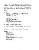
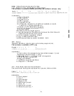
-  Waypoint 

Latitude and 

of 

specified  waypoint 

The  c o n t e n t  

of ?his sentence 

will 

normally be the  position 

of 

t h e  n e x t  waypoint 

in t h e  sailplan.  W h e n  

following 

the 

RTE 

sentence 

the 

positions of 

all 

the 

w a y p o i n t s  

in 

the 

will 

be transmitted. 

f i e l d :  

5 6  

explanation: 

2. 

Waypoint  Latitude 

3. 

North or  South, 

4. 

Waypoint  longitude 

5. 

East or  West, 

6. Waypoint identifier, 

through 

99 

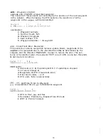
Cross-Track 

Error, 

Measured: 

This  sentence contains navigation receiver  update  status,  magnitude o f  the 

error  perpendicular  t o  the intended track  Dine  as determined 

by 

the 

sailplan, 

and 

the 

direction 

t o  steer  t o  reduce the error.  The sen- 

t e n c e  is transmitted  w h e n  t h e  autopilot 

is 

set t o  

ON, a n d  w h e n  this alarm 

is 

not in alarm condition. 

f i e l d :   2  3 

5 6  

na 

2.  Status 

or 

V, 

if updating 

is 

OK, 

if updating is stopped 

3. n o t  used, always 

4. 

Magnitude 

of 

XTE  (cross-track-error) 

5. Direction t o  steer, 

or 

6. 

XTE  units, 

for  nautical miles 

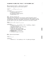
and 

Time 

To  Go to 

Waypoint 

and predicted time t o  

go 

t o  destination  waypoint. 

2.  UTC 

in 

Hour, 

and Sec 

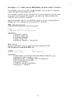
3. 

Estimated,  Predicted 

Elapsed Time 

En  route 

WPT 

or  Point 

of 

Interest. 

Summary of Contents for MK8

Page 1: ...ors Installation Interface Trouble Shooting Maintenance Technical data International Service Special Features aypoint Lists February 1998 3508 101 87993 Specifications may be changed without prior notice ...

Page 2: ...ampered accordingly The availability and precision will be kept within the stated limits as far as the military and political situation allows The MK8 and MK9 are prepared for direct connection to a DGPS Beacon Receiver Philips PBR 1000 The MK8 will for this purpose need a DGPS software upgrade and a new interface cable allowing data input The position accuracy is hereby improved to better than 5 ...

Page 3: ...enance Software Update Technical Data International Service Main Distributors Glossary of Terms About GPS Position Store Feature eknowledge Feature Fast Access to Contrast and Back Light Setting a j t Pass Criteria Waypoint Lists page 4 page 8 page 10 page 1 2 page 19 page 20 page 23 page 25 page 27 page 28 page 32 page 34 page 38 page39 page 39 page42 page 43 3 ...

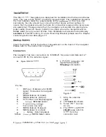
Page 4: ... chapter containing technical data page 27 Insert the battery cell in the battery compartment on the back of the navigator Please refer to the instruction on page 2 1 The navigator has t w o connectors A D SUB A for power and data and a F connector El for the antenna signal A 9 pin D SUB male Pin No 1 2 3 4 5 6 7 8 9 Screen 1 2 3 4 5 SPQLO SUR B F RUG59 connector RF signal from antenna Stripping i...

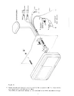
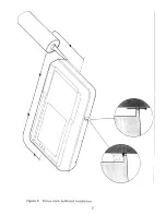
Page 5: ...Figure 2 1 e not inciude in the 2 kit The fuse can IN and cables are not included in the standard packa PO 40 Amp 5 ...

Page 6: ... Please be sure to have a fuse in the circuit not to protect the navigator but to protect the cabling Short circuiting a cable with direct connection to a battery will make severe damage A typical installation is shown in figure 2 page 5 The electronics of the navigator is isolated from the external power supply It is recommended to ground the shield of the navigator to avoid static charge built u...

Page 7: ...7 ...

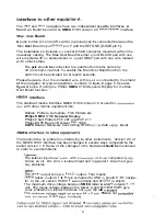
Page 8: ...dard marine interface NMEA 0183 version 2 0 is used for comrnunica tion with other marine equipment like Radars Plotters Autopilots Fish Finders etc Philips NMEA 0183 Repeater Display Philips Chart Plotters PCP 207 and PCP 211 Philips DGPS Beacon Receiver PBR 1000 DGPS Beacon Receivers transmitting RTCM SC104 data d baud There should be no problem in interfacing to other instruments Version 2 0 of...

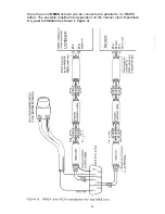
Page 9: ... NMEA listener can be connected in parallel to the NMEA talker The possible maximum is dependent on the listener input impedance A typical installation is shown in figure 4 01 i i L 0 x U CD m I I m W I z L 0 L P m ...

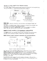
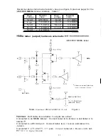
Page 10: ...ay Be careful that neither the NMEA talker B wire nor the shield of the NMEA talker cable are short circuited to each other or anything else V43irSiO atics The NMEA version 2 0 standard requires that a schematic showing the imple mentation of the listener and talker interface are included in the manual 0ther Equipment NMEA Listener NMEA 1NPUT I Figure 6 Listener input load 500ohm threshold of the ...

Page 11: ...11 EA talker output hardware schematic and recornmenoations MK8 MK9 NMEA talker 5v A DATA B Shown in normal position under software control REF GND NMEA POSITION PC V2L POSITION SERVICE ONLY 623V Talker maximum drive current is 78 mA Figure 6 1 Both talker A and talker 6 outputs are active Connected to an NMEA listener Connect talker A to listener A and talker B to listener B Connected to a RS 422...

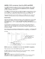
Page 12: ...r except for the first address which is preceded by 5 Hex OD OA C R L F end of sentence must follow the last fieid in each sentence The data fields are identified only by their position within the sentence as determined by the field delimiters comma Numerical data fields within a sentence may vary in length from one sentence to another depending on the precision available Data field position is th...

Page 13: ...12 East or West E W 13 Checksum delimiter and checksum RMB Recommended Minimum Navigation Information Navigation data from present position to the first destination waypoint in the sailplan This sentence always accompanies the RMC when a destination waypoint is selected Checksum is mandatory in this sentence f i e l d 2 3 4 5 6 7 8 9 10 11 12 1 3 15 G P R M B A c c c c c c 11111 I W X X X X X X X ...

Page 14: ...tted empty fields 9 Bearing origin to destination 10 Magnetic M 11 Destination waypoint identifier 12 Bearing present position to destination 13 Magnetic M 14 Heading to steer to destination waypoint 15 Magnetic M BWC Bearing distance to Waypoint Great Circle BWR Bearing distance to Waypoint Rhumb Line Time UTC and distance bearing to and location of the fist destination Waypoint in the sailplan f...

Page 15: ...and mean sea level geoid 12 Units of geoidai separation meters 13 Age of Differential GPS data 14 Differential reference station ID 0000 1023 RTE Routes Waypoint identifiers listed in order with starting waypoint first This sentence is available in MK9 only field 2 3 4 5 6 7 8 GPRTE l l c OO Ol 99 hh CR LF explanation 2 Total number of messages being transmitted always 1 one 3 Message number alway...

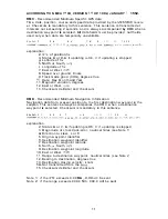
Page 16: ...ver update status magnitude of the posilion error perpendicular to the intended track Dine as determined by the sailplan and the direction RightILeft to steer to reduce the error The sen tence is transmitted when the autopilot alarm is set to ON and when this alarm is not in alarm condition f i e l d 2 3 4 5 6 SGPXTE A A x x x a NcCR LF exptanation 2 Status A or V A if updating is OK V if updating...

Page 17: ...gin waypoint to the next destination waypoint in the sailplan The sentence is transmitted when thE autopilot alarm is set to ON and when this alarm is not in alarm condition field 2 3 4 5 6 9 10 1 1 SGPAPA A A X X X a N xxx M Ccc CR LF explanation 2 Status A or V A if updating IS OK V if updating IS stopped 3 not used always A 4 Magnitude of XTE cross track error 5 Direction to steer L or R 6 XTE ...

Page 18: ...ved WPL sentence WPL Waypoint Location Latitude and longitude of specified waypoint f i e l d 2 3 4 5 6 WPL 111 1 1 1 a yyyyy y y a CCCCCR LF explanation 2 Waypoint Latitude 3 North or South N S 4 Waypoint longitude 5 East or West EIW 6 Waypoint identifier 1 through 99 RTE Routes Waypoint identifiers listed in order with starting waypoint first This sentence is received by MK9 only field 2 3 4 5 6...

Page 19: ...er core a t antenna cable F connec tor Defect antenna cable installation Battery low Internal malfunction Position or time is wrong Back up battery is flat Table 2 Baseband related errors 100 to 109 Real time clock errors 201 to 204 E2ROM related errors 3 0 0 to 303 Oscillator errors 400 to 4 1 0 Action Check battery voItage Check for reverse polarity Check wire installation Check if fuse is blown...

Page 20: ...VIGATOR TEST display b y pressing the up o down key OFF is flashing 3 Press rhe E key 1 4 5 6 Use the up or down key to acti vale the function ON Press the E key to start the self test Software release number Software release date Serial number 1 i Y C 2D BLEEP 24H I C HORE d 20 ...

Page 21: ...leep test will sound E If no errors are found this will be displayed 0 if an error code is displayed note the number and contact your service dealer 1 _ Display numeric test Display dot test e 5 f B 1 p ...

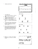
Page 22: ...will stop flashing 9 Press the LEFT key and the LEFT symbol will stop flashing 10 Press the remaining keys and the rest of t h e symbols will stop fiash ing If all symbols have stopped flash ing the keyboard is ok and the display will change to the one shown below If you can not make one or more of the symbols stop flashing by pressing the corresponding keys you should contact your service dealer ...

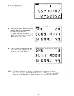
Page 23: ...g example describes how 1 If SAT INFO is ON in SETUP jump to point number 7 2 Select SETUP 3 Scroll up or down with the arrow keys to select the SAT INFO display 4 Press the E key OFF i s flashing POSITION NRUICATE SRtLPLRN U W O I N T RLRRtl BLEEP POSITION NRUICATE SRlLPLRN URYPOINT RLARfl 2 ...

Page 24: ... ratio I NAWICRTE SRLPLRN UFMPOINT ALRRtl SETUP I LRT M t l O R E 8 LON m m NRUICATE SAILPLRN UAYPUINT RLRRH SETUP II R 8 I IlORECE 9 Press the up or down arrow key to see the other displays there are 6 one for each channel nal naise ratio shaufd on open sea e 4 0 if the ELevatian is above 30 degrees If this is not the c may have a bad antenna cable connection or a defective antenna ...

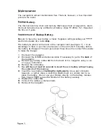
Page 25: ...ged This will give about three times the normal 50 seconds to make the change 1 2 3 4 5 6 7 8 9 Dismount the navigator Dismount the D SUB and antenna cable if necessary to get to the back of the navigator Remove the battery rubber lid from the back of the navigator using a coin or a blunt instrument Remove the old battery Vou will have at least 50 seconds to insert the new battery without loosing ...

Page 26: ...nt the navigator Dismount the D SUB and antenna cable Remove the fuse rubber lid from the back of the navigator using a coin or a blunt instrument Remove the old fuse pulling the nylon strip Inspect the old fuse to test if it is blown If not check the power cable in stallation Place the new fuse in the fuse socket Be sure to get the nylon strip under neath the fuse in order to be able to remove th...

Page 27: ...at controls the navigator The Philips navigator products have always been on the forefront when it comes to yacht navigation This GPS navigator is no exception The navigator is designed so that the control software can be changed or updated without even opening the housing When new software versions become available just bring your navigator to the authorized dealer He will make the upgrade in a m...

Page 28: ...inues tracking Transparent STN Liquid Crystal 8 1 Yellow LEDs Acryl 7N PMMA window Embossed membrane switch 5 keys Polyearbonate ABS PC blend Cycoloy C1200 9 pin male D SUB F female for RG59 Patch with build in preamplifier Not needed Depending of type of antenna Depending of type of antenna SAT4S or RG59 F male twist on for RG59 TNC male Joint pair 0 75 mm2 Shielded pair 0 10 mm2 Shielded pair 0 ...

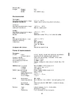
Page 29: ...rence input impedance Activated 6 m 2 m 6 m MK9 only 0OC to 5OoC Splash proof when mounted correctly 1OOC to 70 C Marine waterproof 1OOC to 7OoC Marine Minimum radius 50 mm for antenna cable 2OOC to 7OoC 95 MPT 1204 11 FTZ 171 R47 IEC Recommended 0 5 m CEPT TR 34 01 DC DC switch mode with galvanic separation Less than 5 W display back light on 12 or 24 volt battery 9 6 VDC to 32 VDC A t 0 7 V Fuse...

Page 30: ... To GO Estimated Time of Arrival One sailplan with up to 100 waypoints 100 0 to 99 Antenna open shorted Battery low voltage Position no update Waypoint approach Autopilot Anchor Time 8 Man Over Board MOB NMEA 183 talker sentences Version 2 0 Version 1 5 APB BWR BWC RMB RMC VTG and XTE APA GLL and SNU NMEA 183 listener sentences Version 2 0 1 5 WPL Update Display Every second EA sentences Every two...

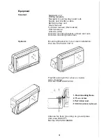
Page 31: ...et Patch Antenna Antenna cable Antenna mounting bracket screws and nuts Antenna mounting instruction Mounting Bracket for below deck installation Part No 9525 200 70710 Optional Flush Mounting Kit for above or below deck mounting Part No 9525 200 70700 1 Flush mounting frame 2 10 pcs screw Antenna for flush mounting on ground plane min area 800 cm Part No 9525 200 08980 31 ...

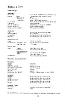
Page 32: ...1 7XD Isle Of Wight Tel 44 1983 282400 Fax 44 1983 280402 recce SeImar Eiectronics Ltd 12 14 Gain Tzelepi GR 18531 Piraeus Fax 30 14 11 95 88 Tlx 241 892 T Tell 30 14 11 95 85 7 32 Holland Sailtron B V Postbus 5044 NL 3502 JA Utrecht Tel Fax 3 i 302 93 76 42 Tlx 40 526 31 302 94 47 41 Hong Kong Radio Holland Group 806 Join In Hang Sing Centre 71 75 Container Port Road Kwai Chuna N T Tel 852 422 39...

Page 33: ... 30 46 Sitelsa S A Via Augusta 186 ES 08021 Barcelona Tel 4 34 34 14 01 92 Fax 34 34 14 25 33 Sweden Sportmanship Marin AB Bolshedens Industrivaeg 30 S 427 22 Bifldal Ttf 46 31 93 94 00 Fax 46 31 91 32 31 Switzerland Bucher Walt Route De Soleure 8 CH2071 St Blake Tei 41 38 35 95 00 Fax 41 38 35 95 30 Turkey Beyoglu Gumussuyu Bolahenk Sok No 7 1 Taksim Istanbul Tel 90 21 22 39 10 29 90 21 22 93 28 ...

Page 34: ...ND COMFASS HEADING Compass reading before correction for deviation and variation COURSE The horizontal direction in which a vessel is steered or intended t o be steered expressed as angular distance from north clockwise through 360 Strictly the term applies to direction through the water not the direction intended to be made good over the ground The course is often designated as true f l i or comp...

Page 35: ...10 minutes may be a good starting point FUNCTI0N A specific operational capability of the navigator GLOBAL POSiTlONING SYSTEM GPS The NAVSTAR Global Positioning System which consists of orbiting satellites a network of ground control stations and user positioning and navigation equipment When fully operational the system will have 21 plus 3 active spare satellites in six orbital planes about 20 20...

Page 36: ...erein the curved surface of the earth s ellipsoid is projected onto a cylinder and the cylinder is unwrap form a flat representation of the ellipsoid earth model NMEA National Marine Electronics Association The NMEA electronics interface speci fications have been developed under the ouspices of the Association The NMEA 0183 is an internationally recognized specifications for interfacing marine ele...

Page 37: ...4 longitudinal segments around the world each generally 15 degrees and 1 hour wide In some regions there are half hour time zones TRUE HEADING Direction in relation to true north True heading is compass heading corrected for MAGNETIC VARIATION and deviation TRUE NORTH Direction along the meridian of the observer to the north pole UNIVERSAL TIME C00RDINATED UTC Greenwich mean time corrected for pol...

Page 38: ...wide basis with no direct charge SPS will be provided on the GPS L1 frequency which contains a course acquisition C A code and a naviga tion data message SPS is planned to provide the capability to obtain horizontal position accuracy within 100 meters 2drms 95 percent probability and 300 meters 99 99 percent probability The GPS L 1 frequency also contains a preci sion PI code that is not part of t...

Page 39: ...of the waypoint will be displayed for a few seconds e g number 90 ____ J i 1 2 The next time the button is pressed the new position is stored in the next waypoint location here number 91 3 Each time the button in pressed the o i n is stored in the next ti waypoint 98 a v i a t o r will UPT then start with w a i n 30 again 4 Each time a Dosition is stored the old ertistingjdata are overwritten If y...

Page 40: ...Pre th E key The fir LAT is flashing t digit in Press the left arrow key Now the last digit in WPT is flashing Use the up or down arrow key to change the last digit of the waypoint number Press the left arrow key The first digit in WPT is flashing Use the up or down arrow key to change the digit 7 Press the E key to exit 1 POSlTlOEl NA J ATE SFtllPLAN AtFum SETUP UPT 8 F LAT E LON WPT I Bs N LAT m...

Page 41: ...ccommodate different viewing conditions The following example describes how 1 Select SETUP 2 Scroll up or down with the arrow keys to the CONTWLIGHT display 3 Press the E key First digit CONTRast is flashing 4 Press the up or down key and the contrast of the display will change The CONTRAST can be set on a scale of 1 throu 5 Press the left or r key to Q ...

Page 42: ...A W ti v 42 ...

Page 43: ......

Page 44: ......

Page 45: ...e ...

Page 46: ...oint Lis 46 ...

Page 47: ......

Page 48: ...P ...

Reviews: