172
Summarized manual for FLIM experiments
17.12
Measuring the Instrument Response Function (IRF)
For accurate measurements of lifetimes near to the timing resolution, the instrument
response function (IRF) should be taken into account. The width of the IRF displays the
timing resolution of the instrument.
For determination and use of the instrument response function (IRF) in MP systems with HyD
RLD, it is advisable to place a black, non-reflective piece of paper between the specimen
and the condenser.
17.12.1
Preparing IRF Measurements
There are different ways to obtain an IRF.
17.12.1.1
Estimating the IRF
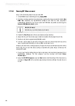
The IRF function normally has to be measured separately. However, SymPhoTime can also
measure the IRF function starting from the ascending edge of the TCSPC decay curve.
17.12.1.2
With Reflection Mode
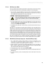
Only use the reflection mode if no suitable fluorescence specimen is available. It might
create additional signals not relevant in real fluorescence experiments. Aside from that, the
IRF is dependent on the wavelength APD.
1. Position a backscattering specimen (such as a cover slip or a mirror) in the laser focus
on the specimen stage of the microscope. Alternatively, you can use Ludox or milk in a
measurement chamber.
2. Remove all barrier filters from the emission path so that the laser line used reaches the
detector.
3. For external FLIM detection, remove the band pass filters from the SMD filter cube.
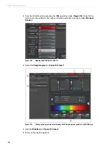
4. Bring the fluorifier disc into the
Substrate
position.
5. Place an OD3 attenuating filter in the filter holder in front of the detector or apply very
low laser intensity. The correct filter holder position can be taken from the detector
manual.
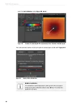
Pay attention to the SymPhoTime online help
Further information can be found in the SymPhoTime online help.
Summary of Contents for TCS SP8 SMD
Page 1: ...10 Living up to Life User Manual Leica TCS SP8 SMD for FCS FLIM and FLCS ...
Page 4: ...4 Copyright ...
Page 14: ...14 Contents ...
Page 18: ...18 Intended Use ...
Page 20: ...20 Liability and Warranty ...
Page 28: ...28 General Safety Notes ...
Page 32: ...32 Additional Notes on Handling the System ...
Page 44: ...44 System Overview and Properties ...
Page 60: ...60 SMD Components Figure 31 DSN 102 Dual SPAD Power Supply ...
Page 80: ...80 Safety Features ...
Page 102: ...102 Switching On the System ...
Page 116: ...116 LAS AF ...
Page 214: ...214 Changing the Specimen ...
Page 216: ...216 Changing the Objective ...
Page 238: ...238 Switching Off the System ...
Page 242: ...242 Repairs and Service Work ...
Page 244: ...244 Maintenance ...
Page 246: ...246 Disassembly and Transport ...
Page 248: ...248 Disposal ...
Page 254: ...254 Contact ...
Page 256: ...256 Recommended Literature ...
Page 266: ...266 Appendix Figure 225 Declaration of conformity ...
Page 268: ...268 Appendix ...
Page 269: ......


