18
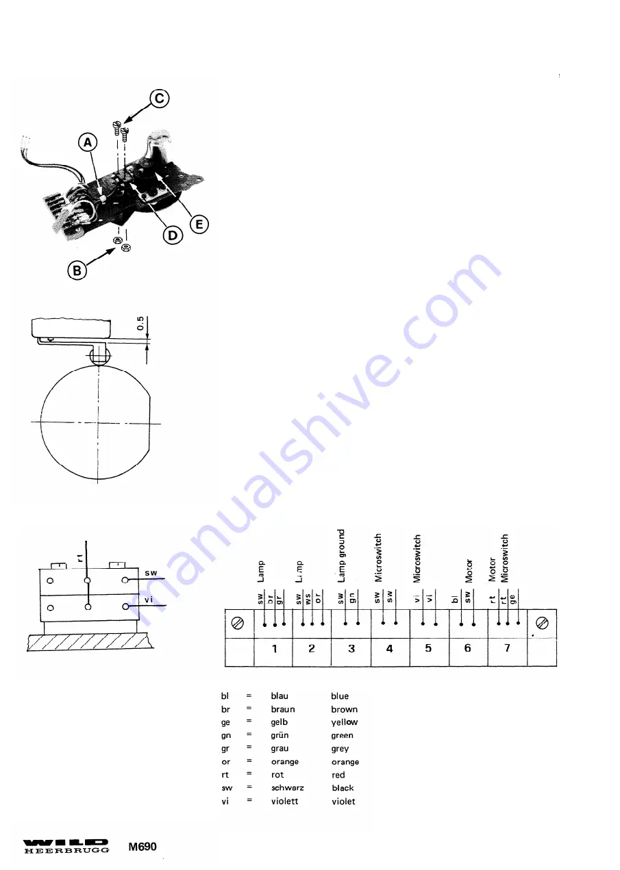
An Klemmleiste Anschlüsse 4,5 und 7,Kabelbinder (A) ,2 Muttern (B)
2 Schrauben (C) und 2 Mikroschalter (D) demontieren.
Montagehinweis:
Mikroschalter (D) schieben und Distanz zwischen Schaltfeder und
Gehäuse von 0,5mm einstellen. Schaltpunkte mit Nockenscheibe (E)
einstellen. Siehe Seite 24.
On terminal strip remove connections 4,5 and 7, cable tie (A) ,2
nuts (B) ,2 screws (C) and 2 microswitches (D).
Assembly instructions:
Displace microswitch (D) to adjust clearance between switch spring
and housing to 0,5mm The switch points of the microswitches are
adjusted by turning came disks (E) , see page 24.
Summary of Contents for WILD M690
Page 1: ......
Page 10: ......
Page 27: ...21...
Page 36: ...Justierung Objektiv A siehe Seite 34 To adjust objective A see page 34...
Page 49: ...Justierung Lampenanschlag siehe Seite 47 To adjust lamp stop see page 47...
Page 64: ......
Page 65: ......
Page 69: ...MSV104 05 94 3691 DMF Service Manual Stands Stages Doc Code 556 913...
Page 71: ...MSV104 Service Manual Stands Stages 05 94 3691 DMF Doc Code 556 913...
Page 75: ...MSV104 05 94 3691 DMF Service Manual Stands Stages Doc Code 556 913...
Page 77: ...MSV104 05 94 3691 DMF Service Manual Stands Stages Doc Code 556 913 X Achse X spindle...
Page 79: ...MSV104 Service Manual Stands Stages 05 94 3691 DMF Doc Code 556 913 Y Achse Y spindle...
Page 83: ...MSV104 Service Manual Stands Stages 05 94 3691 DMF Doc Code 556 913 Notes...
Page 99: ...TUBES VIII 1990 TUBES OPTICS DOC CODE SML 556 917 MTU 108 14...
Page 101: ...TUBES VIII 1990 TUBES OPTICS DOC CODE SML 556 917 MTU 108 16...
Page 103: ...TUBES TUBES OPTICS VIII 1990 DOC CODE SML 556 917 MTU 108 18...
Page 106: ...MTU 108...


