ProVision 3 Installation Manual
8100-35521-00
Rev. A1
Leidos Security Detection & Automation, Inc.
–
Proprietary
Page 61 of 119
© 2020 Leidos. All rights reserved
2.
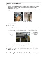
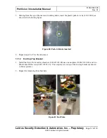
Repeat for the other side of the first outer window.
3.
Repeat Steps 1 and 2 for the second outer window.
11.19
Outer Window Screw Tightening Order
1.
Tighten the top screw of each of the four outer radome bracket supports.
2.
Tighten the bottom screw of each.
3.
Tighten the screws along the outside top and bottom of the two outer radomes.
4.
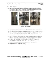
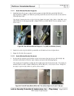
From inside the scanner, tighten the outer radome bracket retainer screws, upper and lower end cap
screws.
11.20
Antenna Operation Verification
CAUTION
It is important to set up a safety area before proceeding. Subsequent installation steps are going to
make the swing arm and masts rotate even though some of the protective barriers (the inner radomes)
have not yet been installed.
E4.10.XX and SS5.1.XX
1.
Connect the Ethernet cable behind the OCP to a field service laptop and turn the field service laptop
on. Wait at least five minutes.
2.
Log in to the field service laptop as sv_admin.
3.
Double-click the
Field Service Tool
icon on the desktop to launch the Field Service Tool program.
4.
Click the
Connect
button at upper right to activate the testing and diagnostics features.
5.
Click
Start SVDiagnostics
on the right side of the Field Service Tool window.
6.
Click on
Calibration
to open the Calibration window.
7.
Click on Pre-cal.
a.
The system performs the motion cal (if this is after power-up) and VCO cal automatically.
b.
If any faults occur. click on LIP reset then click Pre-cal again.
8.
Once complete, a green check appears besides Pre-cal and VCO cal.
9.
Position the calibration beam in the center of the scanner.

