ProVision 3 Installation Manual
8100-35521-00
Rev. A0
Leidos Security Detection & Automation, Inc.
–
Proprietary
Page 115 of 119
© 2020 Leidos. All rights reserved
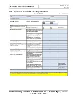
Section
Completed
Task
Install floor cover trim
Determine location for OCP and install OCP mounting bracket
Install two additional OCP mounting brackets for barrier belt
Install top outer radome angle brackets
11.9
Install antenna masts
Route antenna mast cables and connect to ISUs
Clean cosmetic mast wrap with ESD wipes and install
End cap top bracket
Install entrance/exit covers
Install vibration control pads
Peel outer radome scratch guards and clean inner side with ESD wipes
Install outer radomes and clean outer side with ESD wipes
Install outer radome bracket supports
Install middle cover brace bracket U-clips
Install outer radome bracket retainers
Tighten outer radome screws
Verify antenna operation
Install housing brace brackets
Route power cable/other cables; separate and cable-tie if necessary
Install top down power [OPTIONAL] if required.
Install power input box
Install router [optional]
–
refer to 8000-23712-IP
Install remote OCP [optional]
Install roof
Install clip-on panel nuts in top side covers, then install top side covers
Error! R
eference
source
not
found.
Install blank plate and cable pass-through hole/grommet
Install middle OCP cover
Install plain middle cover
11.33
Install middle covers for barrier belt
Install upper/lower cover with switch/power input
Install plain upper/lower covers
Install top entrance/exit covers
Install barrier belt assembly
Install OCP mount pole and OCP
Install label kit
Install system mounted Resolution Station [optional]
Install inner radome top angle rails
Install inner radome base flange support brackets
Peel inner radome scratch guards and clean with ESD wipes
Install inner radome edge support brackets
Install inner radomes
Tighten inner radome screws
Install ceiling
Install ramp supports and ramp assemblies
Install floor side panels and center panel


