ProVision 3 Installation Manual
8100-35521-00
Rev. A1
Leidos Security Detection & Automation, Inc.
–
Proprietary
Page 25 of 119
© 2020 Leidos. All rights reserved
5.2
Leg and Wheelie Bar Attachment
1.
Lay the first of two Genie Lifts horizontally on its wheels.
2.
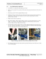
Insert a leg into a square tube leg socket with the casters facing away from the Genie Lift as shown in
Figure 9.
3.
Slide the leg in until it hits the spring-loaded leg lock pin.
4.
Holding onto the leg with one hand, reach under the lift and pull the spring-loaded pin until the leg
starts to drop. Let the pin go, and continue to lower the leg until the pin snaps into the first
captivation hole on the leg.
5.
Repeats steps 2 and 3 for the other leg.
6.
Stand the lift upright. Pull the spring-loaded leg lock pin a second time and slide the leg in a little
further. Let go of the pin, and continue to slide the leg in until the pin snaps into the second
captivation hole on the leg. Repeat for the other leg.
7.
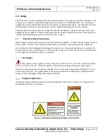
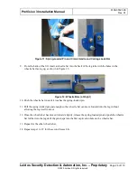
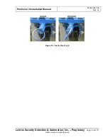
From the back (wheel side) of the lift, remove the crank handle by pulling the spring-loaded pin on
the winch. Rotate the crank handle so it points out and reattach it to the Genie Lift by again pulling
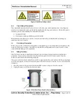
the spring-loaded pin on the winch, as shown in Figure 10.
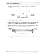
Figure 10: Spring-Loaded Pin and Crank Handle (Rotated from In to Out)
8.
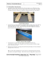
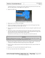
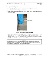
Pull the spring-loaded pin on the carriage lock bar and rotate the bar up and out of the way as shown
in the following figures.

