ProVision 3 Installation Manual
8100-35521-00
Rev. A1
Leidos Security Detection & Automation, Inc.
–
Proprietary
Page 34 of 119
© 2020 Leidos. All rights reserved
8.0 Movement to the Install Location
1.
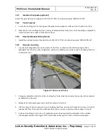
To maintain control when moving the upper/lower frame assembly, Leidos recommends to keep the
two “front” (leading) casters locked unless steering around a corner. Both hands should be kept o
n
the assembly at all times. Move slowly as quick movements can make the assembly uncontrollable.
2.
Slowly push the assembly to the desired location. When turning corners, unlock the front (leading)
casters.
3.
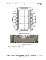
At the install location, orient the assembly so that the electrical enclosure end (see following figure) is
where the operator control panel (OCP) is to be located. This is typically the exit end of the scanner
but can be rotated 180 degrees to be the entrance if desired.
Figure 23: Electrical Enclosure End of Upper/Lower Frame Assembly
4.
If optional seismic brackets (see Section 10.5) are being installed, threaded insert floor anchors might
have been pre-installed into the floor by host facility personnel. If so, position the scanner such that
the brackets will fit over the threaded insert floor anchors.
5.
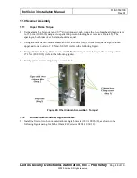
Once the upper/lower frame assembly is in the desired location, the casters may need to be pivoted so
that they are turned in towards the
assembly. The weight of the assembly can make it difficult to
rotate the caster by hand, and it is not recommended. There are several ways to rotate the caster; the
easiest is with a large adjustable wrench or pair of locking pliers.

