ProVision 3 Installation Manual
8100-35521-00
Rev. A1
Leidos Security Detection & Automation, Inc.
–
Proprietary
Page 67 of 119
© 2020 Leidos. All rights reserved
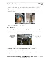
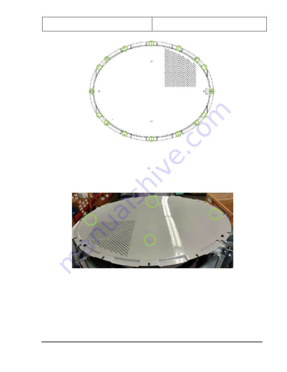
Figure 71: Roof Middle Holes
3.
Install the roof so that the four middle hole (shown circled in green in the following figure) align with
the brackets that are already installed on the upper frame.
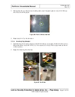
4.
The roof is secured using four M6 x 10mm FBHS screws (0201-22775-10) and four M6 fender
washers (0220-23073-00). Leave screws loose until final cover fitting/alignment.
Figure 72: Roof Middle Holes (Viewed from Motor/Pulley End)
11.28
Top Side Covers
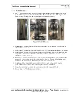
1.
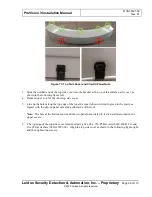
Locate the first of two top side covers (3000-27085-00), shown in the following figure, and install
two clip-on panel nuts (410-23861) in the locations circled in red in the figure; leave the center hole
blank.
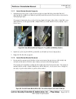
2.
Install the nuts with the flat side toward the outer curve, as shown in the following figure.


